

Bridge Rectifier - Construction, Advantages, Disadvantages, FAQs
Many electronic circuits require a DC power supply to operate, while the available mains supply is AC. A rectifier is used to convert AC into DC, and among all rectifiers, the bridge rectifier is the most efficient. A bridge rectifier is a type of full-wave rectifier that uses four diodes arranged in a bridge configuration to convert alternating current (AC) into direct current (DC). It provides DC output during both half cycles of the input AC signal, resulting in higher efficiency and smoother output. Bridge rectifiers are widely used in power supply circuits, adapters, chargers, and electronic devices. This article explains the construction, working principle, properties, and uses of bridge rectifiers, making it important for Class 12 Physics, JEE, and NEET preparation.
This Story also Contains
- What is a Bridge Rectifier
- Construction of Full Bridge Rectifier-
- Working Of Full Wave Bridge Rectifier
- Full Bridge Rectifier Waveforms
- Ripple factor of Bridge Rectifier of Full Bridge Rectifier-
- Efficiency of Full Bridge Rectifier
- Advantages of Full Bridge Rectifier
- Disadvantages of Full Bridge Rectifier
- Uses of Bridge Rectifier
What is a Bridge Rectifier
A bridge rectifier is an electronic circuit that converts alternating current (AC) into direct current (DC) using four diodes arranged in a bridge form.
In a bridge rectifier, during both the positive and negative half cycles of the AC input, current flows through the load in the same direction. As a result, full-wave rectification is obtained without the need for a centre-tapped transformer.
NCERT Physics Notes :
Construction of Full Bridge Rectifier-
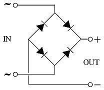
The diagram below depicts the building of a full bridge rectifier. Four diodes D1, D2, D3, D4, and a load resistor RL make up the full bridge rectifier circuit diagram. To efficiently convert alternating current (AC) into direct current (DC), the four diodes are coupled in a closed-loop configuration (DC). The lack of the costly center-tapped transformer is the principal benefit of this design. As a result, both the size and the cost are lowered.
Working Of Full Wave Bridge Rectifier
During the positive half cycle, if you send electricity (AC) across the full bridge rectifier, terminal–A becomes positive, and terminal–B becomes negative. The diodes D1 and D3 become forward-biased at this moment, whereas D2 and D4 become reverse-biased.
During the negative half-cycle, terminal-A becomes positive and the terminal B becomes negative. The diodes D1 and D3 become reverse-biased at this stage, while D2 and D4 become forward-biased.
During both the positive and negative half-cycles, the current flow across the load resistor RL remains constant. The output DC signal's polarity can be completely different. The output can be fully negative or completely positive.
Also read -
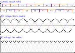
Full Bridge Rectifier Waveforms
When the diodes' direction is reversed, we get a completely negative DC voltage. As a result, both the negative and positive half-cycles of the AC input signal can flow through a diode bridge rectifier.
Ripple factor of Bridge Rectifier of Full Bridge Rectifier-
The ripple factor of the bridge rectifier is a property of the full bridge rectifier that indicates how smooth the output DC signal is. When it comes to the quantity of ripples, we may claim the output DC signal is smooth. The high ripples represent a high-pulsating DC pulse.
The ripple factor of the bridge rectifier is calculated as the ratio of the ripple voltage to the pure DC voltage
Mathematically,
Root Mean Square Voltage = (Vrms)
VDC = DC Supply-Average Voltage
|
Related Topics, |
Efficiency of Full Bridge Rectifier
The measuring of the full bridge rectifier's efficiency reveals the rectifier's best performance. The ratio of DC output power to AC input power is the definition of rectifier efficiency.
$\eta$ = (Output Power DC/input Power AC)
The greatest efficiency of a full bridge rectifier is 81.2 percent.
Advantages of Full Bridge Rectifier
The following are some of the benefits of a full bridge rectifier:
-
The efficiency of full bridge rectifiers is higher than that of half-wave rectifiers
-
A full bridge rectifier produces a smoother output than a half-wave rectifier.
-
For processing, the full bridge rectifier accepts both positive and negative half cycles of the input AC signal. The half-wave rectifier lacks this functionality, processing only half of the AC signal while blocking the other.
Disadvantages of Full Bridge Rectifier
-
When compared to a half-wave rectifier and a center-tapped full-wave rectifier, the circuit of a full bridge rectifier is more complicated. Half-wave rectifiers and center-tapped full wave full bridge rectifiers employ only two diodes, while full-bridge rectifiers use four bridge rectifiers four.
-
When more diodes are utilized, there is a greater loss of power. Only one diode conducts during each half cycle in a center-tapped full-wave rectifier. In a full bridge rectifier, however, each half cycle is conducted by two diodes. As a result, the voltage drop in a full bridge rectifier is larger.
-
The voltage loss in the internal resistance circuit is twice that of the center tap circuit.
-
We may be able to do without a transformer if voltage stepping up or down is not required.
Uses of Bridge Rectifier
- Bridge rectifiers are used in the modulation and demodulation of radio signals.
- They are widely used to convert AC voltage into DC voltage in electronic circuits.
- Used in electric welding to obtain the required DC output.
- Bridge rectifiers mainly act as power supply units in adapters, chargers, TVs, computers, and other electronic devices.
Also, check-
Frequently Asked Questions (FAQs)
Incorporating a series diode shortly after where the positive DC connects to the circuit is the simplest technique to prevent reverse polarity connection. Current will only flow through this diode in series if the DC voltage is applied with the right polarity.
A full bridge rectifier is a device that converts mains AC to DC. Full bridge rectifiers are used in power supplies to provide necessary DC voltages for electronic components or devices.
Excessive forward current and a high reverse voltage are two major cause of bridge rectifiers of diode failure. A shorted diode is usually cause of bridge rectifier by a high reverse voltage, while an open diode is cause of bridge rectifier by an excessive current.
Converting AC electricity to DC power is one of the most common use of bridge rectifiers for diodes. Four diodes are used in the full bridge rectifier to provide a circuit that allows full-wave rectification without the use of bridge rectifier of a center-tapped transformer.
It can be utilized in applications that allow floating output terminals, meaning that none of the output terminals are grounded. The use of a bridge rectifier of a center-tapped transformer is no longer necessary. The transformer is less expensive since it only needs to produce half the voltage of a full wave full bridge rectifier rectifier's comparable center-tapped transformer.
The full bridge rectifier's only drawback is that the output voltage is two diode drops (1.4V) lower than the input voltage. This drawback occurs only in very low voltage power supply. For example, if the peak supply voltage is just 5V, the load voltage will only be 3.6V at its highest point.
Two diode drops are lost during bridge rectification. If a very low alternating voltage must be rectified, this reduces output voltage and restricts the possible output voltage.
