LC Circuit Full Form
What is the full form of LC Circuit?
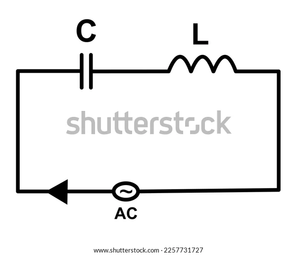
An LC circuit is a type of Electric Circuit that consists of a capacitor and an inductor coupled together. It is also known as a tuned circuit or resonant circuit. The circuit can serve as an electrical tuning fork or resonator by storing energy that oscillates at its resonant frequency.
A bandpass filter is a function that uses LC circuits to either generate signals at a specific frequency or isolate a signal at a specific frequency from a more complex signal. They are essential parts found in several electronic devices, especially radio gear, where they are employed in circuits like oscillators, filters, tuners, and frequency mixers.

Purpose of LC circuits
The function of a bandpass filter is performed by LC circuits, which are used to either generate signals at a specific frequency or isolate a signal at a specific frequency from a more complicated signal.
Their employment in circuits like oscillators, filters, tuners, and frequency mixers makes them essential parts of many electronic devices, notably radio equipment.
Operation of LC circuit.
Electrical energy can be stored in an LC circuit that is vibrating at its natural resonant frequency. Depending on the voltage applied across it, a capacitor stores energy in the electric field (E) between its plates, while an inductor stores energy in the magnetic field (B), based on the current flowing through it.
A magnetic field will form around an inductor if it is connected across a charged capacitor because the voltage across the capacitor will cause a current to flow through it. As the charge is consumed by the current flow, the voltage across the capacitor decreases until it is zero. Because inductors resist changes in current at this point, the magnetic field energy of the coil induces a voltage across the coil. This induced voltage prompts a current to start recharging the capacitor with a voltage that is opposed to the charge it received initially.
Due to Faraday's rule, the energy needed to charge the capacitor is taken from the magnetic field since the EMF that drives the current is brought on by a drop in the magnetic field. The charge will once more be stored in the capacitor with the opposite polarity as before when the current stops and the magnetic field has entirely dissipated. The cycle will then restart, this time with the inductor's current flowing in the opposite direction.
Through the inductor, the charge travels back and forth between the capacitor's plates. If the energy is not replaced by an external circuit, internal resistance causes the oscillations to stop as the energy oscillates back and forth between the capacitor and the inductor.
The tuned circuit acts like a pendulum swinging back and forth or a tank of water sloshing back and forth, and this motion is formally referred to as a harmonic oscillator.
Determining values
The capacitance and inductance values determine the natural frequency, which is the frequency at which it will oscillate when separated from any other system. In the majority of applications, the tuned circuit is a component of a larger circuit that supplies
it with alternating current, causing it to oscillate continuously.
Resonance will happen if the applied current frequency matches the circuit's natural resonant frequency (natural frequency. In this case, a tiny driving current can excite oscillating voltages and currents with enormous amplitudes.
The oscillations in common tuned circuits used in electronic equipment happen very quickly, with rates ranging from thousands to billions per second.
Applications of LC circuit
LC circuits are used to either detect or produce a signal at a particular frequency.
Tank circuits are most frequently used to tune radio transmitters and receivers. For instance, the LC circuits create a resonance for that carrier frequency when you tune a radio to a particular station.
Current magnification is produced via a parallel resonant circuit.
Voltage magnification is produced via a series resonant circuit.
Induction heating uses both parallel and series resonant circuits.
Resonant frequency
When an LC circuit is driven by an outside source at an angular frequency where the magnitudes of the inductive and capacitive reactances are equal, resonance occurs. The resonant frequency for a specific circuit is the frequency at which this equality holds. The LC circuit's resonance frequency is
\omega = \frac{1}{\sqrt{LC}}
![]()
Frequently Asked Questions (FAQs)
Voltage magnification is produced via a series resonant circuit.
Current magnification is produced via a parallel resonant circuit.
Yes, the capacitor stores charge.
Resonance will happen if the applied current frequency matches the circuit's natural resonant frequency.
No, the inductor doesn’t store charge.
Resistor and an inductor.
