

AC Circuit: Definition, Formulas, Terms, Types and applications
Electricity is the most basic phenomenon which is associated with electric current. In electronic circuits, electric current is an important quantity. There are two types of electric currents which are AC (alternating current) and DC (direct current). An alternating current is an electric current whose magnitude changes with time and whose direction reverses periodically. An electric current whose magnitude is either variable or constant but the direction remains the same is called direct current (DC). Direct current can be stored in batteries while alternating current can not be stored.
This Story also Contains
- Components Of AC Circuits
- Important Terms Used In AC Circuits
- Different Types Of AC Circuits
- AC Circuit Containing Resistance And Inductance (RL Circuit):
- Series RLC Circuit:
- Applications Of AC
Components Of AC Circuits
The main components of AC circuits are inductors, capacitors and resistors. These three components are passive components of AC circuits because they continue to consume electrical energy.
Important Terms Used In AC Circuits
Waveform: The nature of the graph of alternating quantity against time is called a waveform.
Amplitude: The maximum value of an alternating quantity in a half cycle is called its amplitude.
Cycle: One complete set of negative and positive values of alternating quantity is known as a cycle.
Frequency: The number of cycles completed by the AC in one second is known as the frequency of AC.
Time Period: The time required to complete one cycle of an alternating quantity is called the time period.
Different Types Of AC Circuits
There are different types of AC circuits such as
The AC circuit with only resistance (R) is called a purely resistive circuit.
The AC circuit with only an inductance (L) is called a purely inductive circuit.
The AC circuit with only capacitance (C) is called a purely capacitive circuit.
AC circuit with the combination of RL (resistance and inductance)
AC circuit with the combination of RLC (resistance, inductance and capacitance)
AC Through Pure Resistive Circuit:
The AC circuit which contains only pure resistance is called a purely resistive circuit. In this type of circuit, the resistors dissipate the power, while the phase of the voltage and current remain the same. A circuit diagram of a purely resistive circuit is shown here.
The instantaneous voltage V ![]() across the resistor R
across the resistor R ![]() is given by, V=V_{m}sin\omega t
is given by, V=V_{m}sin\omega t ![]() and the instantaneous current flowing in the resistor is I=\frac{V}{R}
and the instantaneous current flowing in the resistor is I=\frac{V}{R} 
Now, substituting the value of V ![]() in the above equation,
in the above equation,
We will get I=\frac{V_{m}sin\omega t}{R}=I_{m}sin\omega t
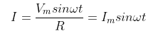
In a purely resistive circuit, the phase angle between voltage and current would be zero.
AC Through Pure Inductive Circuit:
The AC circuit which contains only a pure inductance is called a purely inductive circuit. In this type of circuit, the current lags behind the voltage by an angle of 90 degrees which is shown in the figure given below.
We can say that voltage and current are out of phase with each other by 90 degrees.
AC Through Pure Capacitive Circuit:
The AC circuit which contains only a pure capacitance is called a purely capacitive circuit. In this type of circuit, the current leads voltage by an angle of 90 degrees which is shown in the figure given below.
From the above figure, we can say that voltage and current are out of phase by 90 degrees. When there is an increase in voltage, the capacitor gets charged and reaches its maximum capacity and when there is a decrease in voltage, the negative half cycle happens leading to discharge from the capacitor. The current flow would be zero during maximum voltage and the current starts to flow when the value of voltage decreases to a negative value.
AC Circuit Containing Resistance And Inductance (RL Circuit):
This type of circuit consists of a resistor, an inductor with a pure inductance and an ac power source connected in a series together. A back EMF is generated in the inductor when the switch remains closed. So, the current generally takes more time to reach its maximum value but its magnitude remains the same because the inductor and the resistor are connected in series and the time constant for this circuit is called the inductive time constant which is given by \tau=\frac{L}{R} ![]()
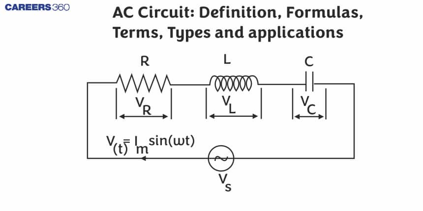
Series RLC Circuit:
This type of circuit consists of a resistor with resistance R, an inductor with a pure inductance and a capacitor with capacitance connected in series to an ac power source. The circuit diagram for this type of circuit is shown in the figure given below.
As we can see from the above diagram,
The voltage across the resistance R
![1707735054751]() is V_{R}=IR
is V_{R}=IR ![1707735054641]() and it is in phase with the current.
and it is in phase with the current.The voltage across the inductance is V_{L}=IX_{L}
![1707735055144]() and it leads the current by an angle of 90 degrees.
and it leads the current by an angle of 90 degrees.The voltage across the capacitor is V_{C}=IX_{C}
![1707735056787]() and it lags the current by an angle of 90 degrees.
and it lags the current by an angle of 90 degrees.
 and it lags the current by an angle of 90 degrees.
Applications Of AC
The following are the applications of AC:
It is used in transport and industrial generation.
It is used in an AC motor which converts alternating current into mechanical power.
It is also used to reduce the voltage in homes and other applications. This can be achieved with the help of a transformer, which transmits power from one inductive coil to another inductive coil.
Frequently Asked Questions (FAQs)
Sources of DC are voltaic cells, dry cells and DC generators. Sources of AC are hydroelectric generators, nuclear power generators and thermal power generators.
The SI unit of inductance is Henry and it is denoted by the symbol H. The SI unit of capacitance is Farad and it is denoted by the symbol F.
Alternating current is dangerous at high voltages and requires insulation. Another disadvantage is that batteries or cells can not be directly charged from the ac source.
The coil which stores magnetic energy in the form of a magnetic field is known as an inductor. So, we can say that it is a device which stores magnetic energy.
The first advantage is that AC is easy to transfer over long distances, while DC can not be transferred over a very long distance. Another advantage is that in AC, the flow of electric current changes its direction forward and backwards periodically, while in DC, it flows in a single direction steadily and AC is less expensive and easy to generate than DC.
