

- Physics
- AC Voltage Applied To A Resistor
AC Voltage Applied To A Resistor
When AC voltage is applied to a resistor, the current through the resistor alternates in phase with the voltage, showcasing the fundamental principles of Ohm's Law in an AC circuit. Unlike other circuit elements like capacitors and inductors, resistors do not cause a phase shift between voltage and current. This behaviour is crucial in various practical applications, such as in heating elements, where resistors convert electrical energy into heat efficiently. Understanding how AC voltage interacts with resistors helps in designing and managing household appliances, industrial machinery, and electronic devices, ensuring their proper function and safety. In this article, we will explore the detailed mechanics and real-life implications of AC voltage applied to resistors.
This Story also Contains
- AC Voltage Applied to a Resistor
- Solved Examples Based on AC Voltage Applied to a Resistor
- Summary

AC Voltage Applied to a Resistor
When a constant voltage source or battery is applied across a resistor current is developed in resister. This current has a unique direction and flows from the negative terminal of a battery to the positive terminal. The magnitude of the current remains constant as well. If the Direction of current through the resistor changes periodically then the current is called alternating current.

Voltage V(t) is applied across resistance R. V(t) is sinusoidal voltage with peak Vm and time period T.
$T=\frac{1}{f}=\frac{2 \pi}{\omega}$
Where f is frequency and ω is the angular frequency. This kind of circuit is a purely resistive circuit. According to Kirchhoff’s law
$\begin{aligned} v(t) & =R i(t) \\ i(t) & =\frac{v(t)}{R} \\ i(t) & =\frac{V_m \sin (\omega t)}{R} \\ i_m & =\frac{V_m}{R} \\ i(t) & =i_m \sin (\omega t)\end{aligned}$
Here voltage and current have the same frequency and both are in the same phase. Therefore, the phase difference between current and voltage is 0.
The maximum value of voltage is achieved at t=T/4.
Peak current ,$i_0=\frac{V_0}{R}$.
Power Factor
The ratio of resistance and impedance. The power factor is also denoted by $\cos \phi$.
power factor $=\cos (\phi)=1$
Power:
$P=V_{r m s} i_{r m s}=\frac{V_0 i_0}{2}$
Time difference
$T. D .=0$
Recommended Topic Video
Solved Examples Based on AC Voltage Applied to a Resistor
Example 1: The phase difference between voltage and current in a purely resistive circuit is
1) $2 \pi$
2) $\pi$
3) $\frac{\pi}{2}$
4) 0
Solution:
Phase difference
The difference between the phase of current and voltage is called phase difference.
In a purely resistive circuit, the angle between voltage and current is 0.
Hence phase difference $\phi=0$
Hence, the answer is the option (4).
Example 2: Calculate the power factor in the given circuit

1) 1
2) 2
3) 4
4) 0
Solution:
The power factor in resistive circuits
$
\cos \phi=1
$
Power factor
$
\begin{aligned}
& \text { Power factor } \cos \phi=\frac{R}{Z} \\
& R=2 k \Omega \\
& Z=\sqrt{R^2+\left(X_L-X_C\right)^2}=R \quad\left(X_L=X_C=0\right) \\
& \therefore \cos \phi=1
\end{aligned}
$
Power factor $=1$
Hence, the answer is the option (1).
Example 3: The phase difference in a resistive circuit is
1) 0
2) $\frac{\pi}{2}$
3) $\pi$
4) $2 \pi$
Solution:
The power factor in resistive circuits
$
\begin{aligned}
\cos \phi & =1 \\
\cos \phi & =\frac{R}{Z}
\end{aligned}
$
For purely resistive circuit
$
\begin{aligned}
& \mathrm{Z}=\mathrm{R} \\
& \therefore \cos \phi=1 \\
& \Rightarrow \phi=0
\end{aligned}
$
Hence, the answer is the option (1).
Example 4: For a resistive circuit only, the time difference is
1) 0
2) $\frac{T}{2}$
3) $\frac{T}{4}$
4) None
Solution
Time Difference $=\frac{T}{2 \pi} \times \phi$
For purely resistive circuit $\phi=0$
Therefore, Time Difference $=0$
Hence, the answer is the option (1).
Example 5: Given fig satisfies which of the following electrical circuits?
![]()
1) Inductive Circuit
2) Capacitive Circuit
3) Resistive Circuit
4) None
Solution:
Phasor diagram
Both are on the same plane
wherein
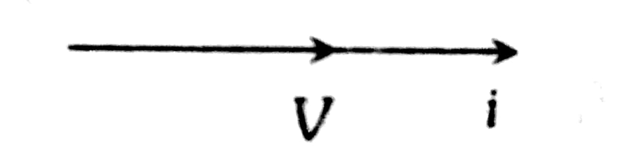
This shows that the phase difference between V and i is 0.
This is the case only for resistive circuits.
Hence, the answer is the option (3).
Summary
When AC voltage is applied to a resistor, the current alternates in phase with the voltage, as governed by Ohm's Law. This results in no phase difference between current and voltage, a crucial aspect for various applications such as heating elements and electronic devices. Understanding this relationship helps in designing efficient and safe electrical systems. The power factor in such circuits is 1, and both voltage and current reach their peaks simultaneously, ensuring effective energy transfer.
Recommended eBooks
Related eBooks and Sample Papers
25 Oct'25 - 15 Jun'26 (Online)
1 Nov'25 - 8 Jun'26 (Online)
22 Dec'25 - 21 Jun'26 (Online)
29 Dec'25 - 6 Jun'26 (Online)
11 Feb'26 - 18 Aug'26 (Online)

News and Notifications
Student Community: Where Questions Find Answers