AC Voltage Applied To An Inductor
When an alternating current (AC) voltage is applied to an inductor, the behaviour of the inductor is characterized by its ability to resist changes in current. An inductor, essentially a coil of wire, stores energy in its magnetic field when current flows through it. The relationship between AC voltage and current in an inductor is governed by its inductive reactance, which varies with the frequency of the AC signal. This phenomenon is crucial in many real-world applications, such as in power supplies, where inductors help smooth out fluctuations in current, and in radio-frequency circuits, where they play a role in tuning and filtering signals. In this article we will Understand how AC voltage interacts with inductors is key to designing and optimizing electrical and electronic systems.
This Story also Contains
- AC Voltage Applied to an Inductor
- Solved Examples Based on AC Voltage Applied to an Inductor
- Summary
AC Voltage Applied to an Inductor
When an alternating current (AC) voltage is applied to an inductor, the inductor's reaction is characterized by its inductive reactance, which opposes changes in current flow. An inductor, typically a coil of wire, generates a magnetic field when current flows through it. This magnetic field resists changes in the current, leading to a phase difference between the voltage across the inductor and the current flowing through it. The voltage across an inductor in an AC circuit is directly proportional to the rate of change of current, and the inductive reactance increases with the frequency of the AC signal.
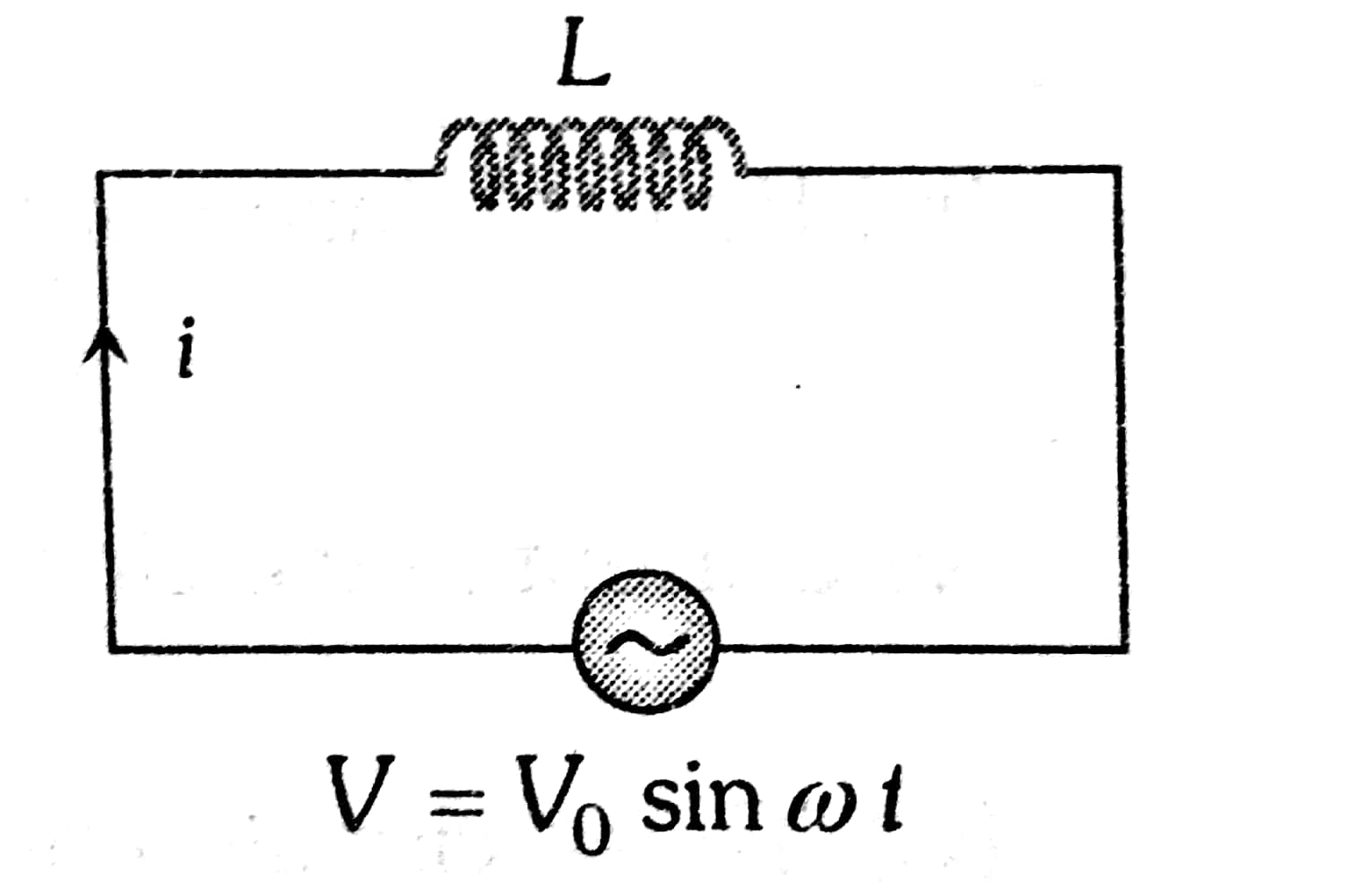
The voltage applied in the circuit is $V=V_0 \sin \omega t$ and is applied to a pure inductor coil of inductance L. As the current through the inductor varies opposing induced emf is generated in it and is given by $-L \frac{d i}{d t}$.

From Kirchhoff's loop rule:
$
V_0 \sin \omega t-L \frac{d i}{d t}=0
$
or
$
d i=\frac{V_0}{L} \sin \omega t d t
$
Integrating both sides we get,
$i=-\frac{V_0}{\omega L} \cos \omega t+C$
Where C is the constant of integration, this integration constant has dimensions of current and is independent of time. Since the source has an emf which oscillates symmetrically about zero, the current it sustains also oscillates symmetrically about zero, so there is no time-independent component of current that exists. Thus constant C=0.
So we have,
$\begin{aligned} i & =\frac{-V_0}{\omega L} \cos \omega t \\ & =\frac{V_0}{\omega L} \sin \left(\omega t-\frac{\pi}{2}\right) \\ i & =i_0 \sin \left(\omega t-\frac{\pi}{2}\right)\end{aligned}$
Where $i_0=\frac{V_0}{\omega L}$ is called the peak value of the current.
From instantaneous values of current and voltage, we see that in the pure inductive circuit the current lags behind emf by a phase angle of π/2.
This phase relationship is graphically shown below in the figure

Since the peak value of current in the coil is $i_0=\frac{V_0}{\omega L}$.
Comparing it with Ohm's law we find product ωL has the dimension of resistance and it can be represented by
$X_L=\omega L$
where XL is known as reactance of the coil which represents the effective opposition of the coil to the flow of alternating current.
Phase difference (between voltage and current)
$\phi=+\frac{\pi}{2}$
Power factor
$\cos (\phi)=0$
Time difference
$\mathrm{T} . \mathrm{D}=\frac{T}{4}$
Recommended Topic Video
Solved Examples Based on AC Voltage Applied to an Inductor
Example 1: A circuit has a resistance of 12 ohms and an impedance of 15 ohms. The power factor of the circuit will be
1) 0.8
2) 0.125
3) 1.25
4) 0.4
Solution:
R.L Circuit Voltage
$\begin{aligned} & V_R=I R \\ & V_L=I X_L\end{aligned}$
wherein

Power factor
$\cos \phi=\frac{R}{\sqrt{R^2+X_c^2}}$
Capacitive current (C) Current
$i^{\prime}=i_0^{\prime} \sin \left(\omega t+\frac{\pi}{2}\right)$
wherein

Inductive circuit (L) Current
$i^{\prime}=i_0^{\prime} \sin \left(\omega t-\frac{\pi}{2}\right)$
wherein
Power factor $\cos \phi=\frac{R}{Z}=\frac{12}{15}=0.8$
Hence, the answer is the option (1).
Example 2: A sinusoidal voltage V(t) = 100 sin (500t) is applied across a pure inductance of L = 0.02 H. The current through the coil is :
1) $10 \cos (500 t)$
2) $-10 \cos (500 t)$
3) $10 \sin (500 t)$
4) $-10 \sin (500 t)$
Solution:
We know that voltage across inductor
$
\begin{aligned}
& V=L \frac{d i}{d t} \\
& i=\frac{1}{L} \int 100 \sin (500 t) \mathrm{dti}=-10 \cos 500 t
\end{aligned}
$
Hence, the answer is the option (2).
Example 3: Phase difference b/w voltage & current in inductive circuit is
1) 0
2) $\frac{\pi}{2}$
3) $\frac{\pi}{4}$
4) $\pi$
Solution:
The phase difference between voltage and current
$\phi=90^{\circ}$ or $(+\pi / 2)$
for inductive circuits, voltage leads the current by $\frac{\pi}{2}$

Hence, the answer is the option (2).
Example 4: The power factor for the inductive circuit is
1) 0
2) 1
3) 2
4) 0.5
Solution:
Power factor
$\cos \phi=0$
The phase difference $(\phi)$ between voltage & current is $90^{\circ}$ in an inductive circuit. T
$\Rightarrow$ Power factor, $\cos \phi=\frac{R}{Z}$
Cos90=0
Power factor=0
Hence, the answer is the option (1).
Example 5: Calculate the power in a given circuit

1) $V_0 I_o$
2) $\frac{V_o I_o}{2}$
3) $\frac{V_o I_o}{\sqrt{2}}$
4) 0
Solution:
Power
$\begin{aligned} & P=0 \\ & \text { Power }=\frac{V_o I_o}{2} \cos \phi\end{aligned}$
In a purely inductive circuit, the voltage leads current by $\frac{\pi}{2}$ phase $(\phi)$
$\begin{aligned} & P=\frac{V_o I_o}{7} \cos \frac{\pi}{2} \\ & \mathrm{P}=0\end{aligned}$
Hence, the answer is the option (4).
Summary
When an AC voltage is applied to an inductor, the current lags the voltage by a phase angle of 90 degrees due to the inductor's inductive reactance. This reactance opposes changes in current and increases with the frequency of the AC signal. In real-world applications, such as in power supplies and radio-frequency circuits, inductors help stabilize current and filter signals. The inductive reactance's behaviour is critical in designing efficient electrical and electronic systems.