Ampere's Circuital Law And Its Applications
Imagine winding a wire around a nail and making an electromagnet. How would you calculate the magnetic field around the wire? Ampere's circuital law creates a relation between the flowing electric current and the consequent magnetic field produced. It forms one of the base principles of electromagnetism, critical for designing electric motors and transformers, among many others. Let's see how Ampere's Circuital Law can read the output of a wound circuit amongst other things in electronics and magnetism.
New: JEE Main/NEET 2027 - Physics Important Formulas for Class 10
JEE Main 2025: Study Materials | High Scoring Topics | Preparation Guide
JEE Main 2025: Syllabus | Sample Papers | Mock Tests | PYQs | Study Plan 100 Days
NEET 2025: Syllabus | High Scoring Topics | PYQs | Crack NEET in 2 months - Study Plan
- Ampers Circitue Law
- Magnetic Field Due to Infinitely Long Cylindrical Wire Due to Current 'i' Distributed Uniformly Across Its Cross-Section
- Solved Example Based On Ampere's Circuital Law And Its Applications
- Summary
Further, we discuss in this article, Ampere's Circuital Law And Its Applications is important for board exams and comparative exams. This concept is in the class 12th Magnetic Effects of Current and Magnetism chapter. Questions asked from these competitive exams like the JEE Main, NEET, and other entrance exams such as SRMJEE, BITSAT, WBJEE, BCECE and more. Over the last ten years of the JEE Main exam (from 2013 to 2023), a total of seventeen questions have been asked on this concept. And for NEET five questions were asked from this concept.
Ampers Circitue Law
Amperes law is also a method to calculate the magnetic field due to a given current distribution like Biot-Savart's law.
Statement: The line integral of the magnetic field $\vec{B}$ around any closed curve is equal to $\mu_0$ times the total current i passing through the area enclosed by the curve.
Mathematical statement: $\oint \vec{B} d \vec{l}=\mu_0 \sum i=\mu_0\left(i_1+i_3-i_2\right)$
Also using $\vec{B}=\mu_0 \vec{H} \quad \ldots($ where $\vec{H}=$ magnetising field $)$
$
\oint \mu_0 \vec{H} \cdot \overrightarrow{d l}=\mu_0 \Sigma i \Rightarrow \oint \vec{H} \cdot \overrightarrow{d l}=\Sigma i
$

Fingers are curled in the loop direction, the current in the direction of the thumb is taken as positive whereas in the direction opposite to that of the thumb is taken as negative.
Now, we can see that the total current crossing the above area is $\left(i_1+i_3-i_2\right)$, so any current outside the given area will not be considered. So we have to assume
(Outward $\odot \rightarrow+v e$, Inward $\otimes \rightarrow-v e$ )
General Guidelines for the Selection of Ampere's Path for its Application in Different Situations
(i) Path should be chosen in such a way that at every point of the path magnetic induction should be either tangential to the path elements or normal to it so that the 'dot' product can be easily handled.
(ii) Path should be chosen in such a way that at every point of the path magnetic induction should either be uniform or zero so that calculations become easy.
Application of Ampere's law
Magnetic field due to infinite straight wire -
As by Biot-savant law, we have calculated the magnetic field. Now with the help of Ampere's circuital law, let us take an infinite straight wire, now if we want to calculate the magnetic field of this wire at a distance of 'd' from the wire. Then,
$\oint \vec{B} \cdot \overrightarrow{d l}=\mu_o \cdot i_{\text {inside }}$

See the figure given below, it represents the magnetic field produced by the current-carrying wire and the length vector. We can see that the ' B ' and 'dl' are making an angle 0 degree, so the $\operatorname{Cos} \theta=1$

Also, B is constant as the current is constant which is flowing through the wire. So we can write that -
$B \oint d l=\mu_o \cdot i$
Now the length of the loop is the circumference of the loop. Here the radius is 'd' and full integration of 'dl' is equal to $2 \pi d$. So we can write that -
$\begin{aligned} & B .2 \pi d=\mu_o i \\ & B=\frac{\mu_o i}{2 \pi d}\end{aligned}$
One can notice that the result obtained is the same as that we have obtained by Biot-savant law.
Magnetic Field Due to Infinitely Long Cylindrical Wire Due to Current 'i' Flowing Through Its Surface Only
Let us consider an infinitely long cylindrical wire of radius R and the current is distributed on the surface of the wire, then this wire will behave as a hollow cylindrical wire.

Now let us take different situations -
a) For a point inside the wire - (r<R)

From the top view, the Ampere's loop will look like this -

Since there is no current inside the Ampere's loop, so there will be no magnetic field in this loop because -
$\oint \vec{B} \cdot \overrightarrow{d l}=\mu_0 i$
b) For a point outside the wire (r>R) -
Then from the top, it can be seen as -

It is just like the concept of a current carrying wire which we have studied in the last concept with the help of Ampere's circuital law as well as by Biot-savart law. So again by applying same Ampere's circuital law we can deduce that -
$
B=\frac{\mu_o i}{2 \pi r}
$
c) On the surface $(\mathrm{r}=\mathrm{R})$
$
B_s=\frac{\mu_o i}{2 \pi r}
$
From the above equations, we can plot a graph between B and different positions 'r'.

Magnetic Field Due to Infinitely Long Cylindrical Wire Due to Current 'i' Distributed Uniformly Across Its Cross-Section
Magnetic field due to a cylindrical wire is obtained by the application of Ampere's law. Here also we consider few cases one by one -
a) Outside the cylinder -

It is just like the concept of a current carrying wire which we have studied in the last concept with the help of Ampere's circuital law as well as by Biot-savart law. So again by applying same Ampere's circuital law we can deduce that -
$B=\frac{\mu_o i}{2 \pi r}$
b) Inside the solid cylinder : Current enclosed by loop (i') is lesser then the total current (i) -

Since the current density will remain the same.
So,
$
J=J^{\prime} \Rightarrow \quad i=i \times \frac{A^{\prime}}{A}=i\left(\frac{r^2}{R^2}\right)
$
Hence at inside point $\oint \overrightarrow{B_{\text {in }}} \cdot d \vec{l}=\mu_0 i \Rightarrow B=\frac{\mu_0}{2 \pi} \cdot \frac{i r}{R^2}$
c) At surface (r=R) -
$B_s=\frac{\mu_o i}{2 \pi r}$
The variation of B with r can be drawn as -

Solved Example Based On Ampere's Circuital Law And Its Applications
Example 1: Two wires with current 2A and 1A are enclosed in a circular loop. Another wire with current 3A is situated outside the circular loop. The $\int B \cdot \overrightarrow{d l}$ around the loop is:

1) $\mu_0$
2) $3 \mu_0$
3) $6 \mu_0$
4) $2 \mu_0$
Solution:
As we learned
Ampere's Law -
It gives another method to calculate the magnetic field due to the given current distribution.
Another wire with current 3A is situated outside the loop as shown-
According to Ampere's circuital law
$\oint \vec{B} \cdot \overrightarrow{d l}=\mu_0 I_{\text {enclosed }}=\mu_0(2 A-1 A)=\mu_0$
Example 2: A current I flows along the length of an infinitely long straight and thin-walled pipe then
1) $\vec{B}$ at all points inside the pipe is the same but non-zero
2) $\vec{B}$ at any point inside the pipe is zero
3) $\vec{B}$ is zero only at the axis of the pipe
4) $\vec{B}$ is different at different points
Solution:
As we learned
Ampere's Law
It gives another method to calculate the magnetic field due to the given current distribution.

Amperian loop of radius r inside cylinder
Applying Ampere's law
For closed path.
$\mathrm{I}=0$ inside pipe
So $\vec{B}=0$ for every point
Example 3: A large metal sheet carries an electric current along its surface current per unit length is $\lambda$. Magnetic field induction near the metal surface is

1) $\lambda \mu o$
2) $\frac{\lambda \mu o}{2}$
3) $\frac{\lambda \mu o}{2 \pi}$
4) $\frac{\mu o}{2 \pi \lambda}$
Solution:
As we learned
The magnetic field in the Infinite sheet carrying current -
$
B=\frac{\mu_o j}{2}
$
$J \rightarrow$ current density
- wherein
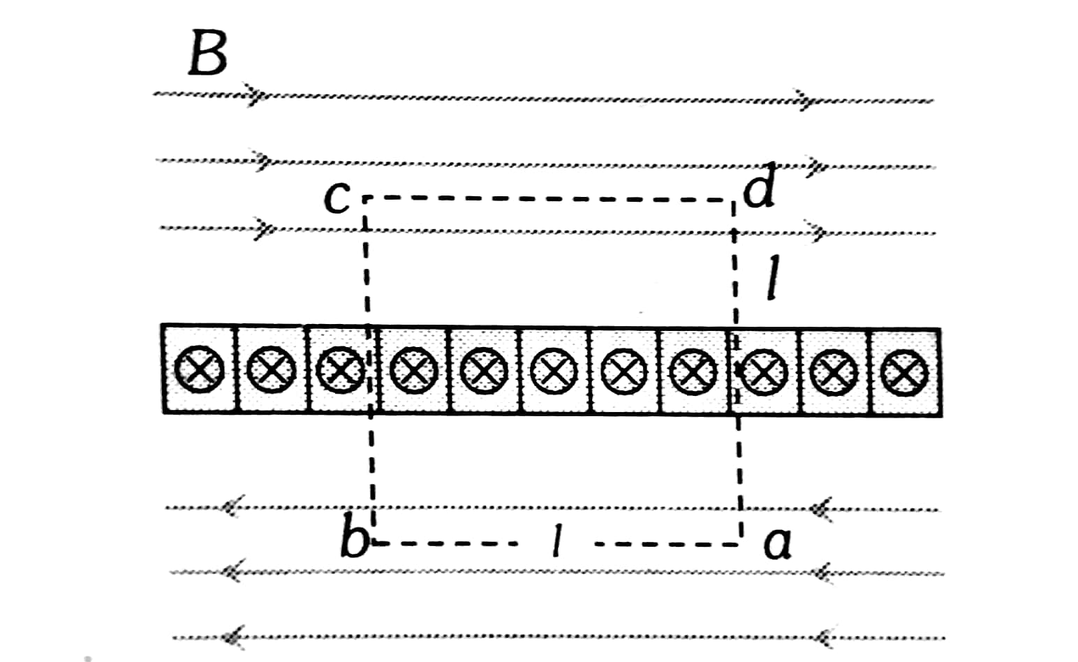
Use ampere circuital law
$\begin{aligned} & \oint \vec{B} \cdot \overrightarrow{d l}=\mu o I \\ & 2 B l=\mu o(\lambda l) \\ & B=\frac{\mu o \lambda}{2}\end{aligned}$
Example 4: The figure shows an amperian path $A B C D A$ Part $A B C$ is in the vertical plane PSTU while part $C D A$ is in the horizontal plane $P Q R S$. The direction of circulation along the path is shown by an arrow near points $B$ and $D$.
$\oint \vec{B} \cdot \overrightarrow{d l}$ for this path according to Ampere’s law will be :

1) $\left(i_1-i_2+i_3\right) \mu_0$
2) $\left(-i_1+i_2\right) \mu_0$
3) $i_3 \mu_0$
4) $\left(i_1+i_2\right) \mu_0$
Solution:
$\oint_{A B C D A} \vec{B} \overrightarrow{d l}=\mu_0\left(i_1+i_3+i_2-i_3\right)=\mu_0\left(i_1+i_2\right)$
[Since for the given direction of circulation $i_3$ entering at PSTU is positive while $i_3$ at PQRS is negative]
Example 5: A long-walled pipe of radius R carries a current i along its length. The current density is uniform over the circumference of the pipe. The magnetic field at the centre of the pipe due to the quarter portion of the pipe shown, is

1) $\frac{\mu_0 i \sqrt{2}}{4 \pi^2 R}$
2) $\frac{\mu_{0 \mathrm{i}}}{\pi^2 R}$
3) $\frac{2 \mu_0 i \sqrt{2}}{\pi^2 R}$
4) None
Solution:

$\begin{aligned} & \lambda=\frac{i}{2 \pi r} \\ & d i=\lambda \cdot R d \theta \\ & d B=\frac{\mu_0 \lambda R d \theta}{2 \pi R} \\ & B_{\perp}=\int_0^{\pi / 2} d B \sin \theta=\frac{\mu_0 \lambda}{2 \pi}=\frac{\mu_0 i}{4 \pi^2 R} \\ & B_{11}=\int_0^{\pi / 2} d B \sin \theta=\frac{\mu_0 i}{4 \pi^2 R} \\ & B_{\text {net }}=\sqrt{2} \frac{\mu_0 i}{4 \pi^2 R} \quad\left(\because B_{\text {net }}=\sqrt{\left(B_{\perp}\right)^2+\left(B_{11}\right)^2}\right)\end{aligned}$
Summary
Ampere's Circuital Law says that a magnetic field in space around the electric current is proportional to the current itself. In general, it relates the integrated magnetic field around a closed loop to the electric current passing through the loop. It is expressed as the integral of the magnetic field around a closed path equating to the permeability of free space times the current enclosed by the path. In this law wide applications in the design of electromagnets, analysis of magnetic field in electrical circuits, and study of inductor and transformer behaviours.
Also Read
28 Nov'24 05:07 PM
17 Nov'24 09:58 AM
26 Sep'24 11:51 AM
26 Sep'24 11:48 AM
26 Sep'24 11:45 AM
25 Sep'24 01:20 PM
25 Sep'24 01:13 PM
25 Sep'24 01:12 PM
25 Sep'24 01:12 PM
25 Sep'24 12:58 PM