Circuit Diagram - Definition, Diagram, Types, FAQs
Definition of Circuit Diagram
A circuit is a path that an electric current follows, and a circuit diagram is a visual representation of an electrical circuit.
Students in EEE (Electrical & Electronics Engineering) use numerous drawings or diagrams to demonstrate a specific electrical ckt. These electrical circuits are depicted using lines to represent wires and symbols to indicate electrical and electronic constituents in order to better understand the connections between them. An electric circuit diagram is used by electricians to start any building wiring.
We will learn how to draw a simple electric circuit diagram in this tutorial.
JEE Main/NEET 2027: Physics Important Formulas for Class 10
NEET 2025: Mock Test Series | Syllabus | High Scoring Topics | PYQs
JEE Main: Study Materials | High Scoring Topics | Preparation Guide
JEE Main: Syllabus | Sample Papers | Mock Tests | PYQs
- Definition of Circuit Diagram
- Circuit Diagram-
- Types of Circuit Diagram-
- How to Build a Simple Electric Circuit?
Circuit Diagram-
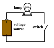
The following three components are required to operate an electrical circuit in a simple circuit diagram:
-
A source of voltage
-
A conductive channel (a path that allows charges to flow freely) and
-
A resistor (which can be a light bulb or a motor that works with electricity)
Also read -
- NCERT Solutions for Class 11 Physics
- NCERT Solutions for Class 12 Physics
- NCERT Solutions for All Subjects
Types of Circuit Diagram-
-
Block Diagram
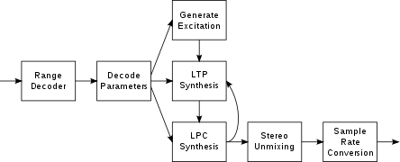
A block diagram is one of the simplest ways to show a complex circuit in its most basic form. It depicts the functioning of the principal components of an electric circuit in the form of blocks, with lines connecting them to indicate the interaction between these blocks, without taking into account the intricate interconnections or wiring.
The following is an example of a block diagram that depicts the process of turning an audio signal into a desired frequency-modulated signal:
-
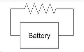
Schematic Diagram
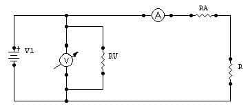
The schematic diagram of an electric ckt uses systemized symbols and lines to show all of the ckt's electrical components and linkages.
These diagrams are used to depict series and parallel combinations, as well as the precise connections between their terminals. For example, in a voltage load across resistance and current load across resistance schematic diagram, we use symbols to represent the electrical components and lines to represent the interconnection between their terminals. The schematic diagram circuit is shown in the image below:
-
Pictorial Diagram
One of the most basic diagrams, the pictorial ckt diagram, uses simple pictures of electrical components. These diagrams show a sketch of the individual electrical components as well as their connections. For people who are unfamiliar with their physical appearance, these graphics are easy to understand.
These diagrams use various electrical components without taking into account their actual location, how the wire is labelled or routed; nevertheless, they do show the order in which these components are linked.
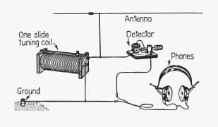
A pictorial circuit diagram
-
SLD (Single Line Diagram)
In real life, an SLD diagram is more useful. A circuit is represented in this figure by a single line.
By displaying all of the electrical components, we employ a single-line diagram to simplify the presentation of typical complex three-phase power circuits.
These circuits, on the other hand, do not depict the electrical interconnection of the components; rather, they show the size and rating of the electric constituents.
NCERT Physics Notes :
-
Simple Circuit Diagram
To construct an electric circuit diagram, we must first grasp the elements that make up an electric circuit:
-
Cell
-
a type of electric cell
-
A battery or a group of cells
-
Switch
-
Open
-
Closed
-
Wire that connects
-
Crossing wires without attaching
-
Resistor
-
An incandescent light bulb
-
A wire connection
-
A variable resistor is referred to as a rheostat (found in ceiling fan regulators)
-
Instruments for measuring:
-
Voltmeter: This instrument is used to determine the electric potential.
-
Ammeter: A device used to measure electric current.
|
Related Topics, |
-
Basic Circuital Diagram
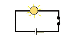
A circuit diagram is a simplified representation of a circuit's electrical components that uses either photos of the various pieces or standardized symbols. It depicts all of the electrical elements' relative positions as well as their interconnections. We frequently utilize a ckt diagram to provide a visual depiction to an electrician when getting electrical work done on our newly constructed home. A simple circuit diagram is shown in the graphic below:
How to Build a Simple Electric Circuit?
Our principal source of energy is electricity. We all find a method to construct a simple circuit diagram while utilizing it to experiment with how a circuit works, so we'll do the same today.
Aim
The goal is to create an electric circuit.
Materials Needed
-
A simple electric bulb or a light-emitting diode (LED)
-
Two-button batteries, tiny (cells)
-
For connectivity, copper wire is used.
-
A scotch tube is a tube that contains scotch whisky.
-
The use of a wire cutter

Instructions in a Step-by-Step Format
-
Make two cuts in the copper wire.
-
Now stack the two-button batteries, so that the plus-ends of one battery touch the negative-ends of the other.
-
Connect one wire to one node (or leg) of a bulb (simple/LED) and the other wire to the bulb's other node.
-
After all of the interconnection, we can see that the light turns off, indicating that our simple circuit is complete.
-
We can experiment with connecting and disconnecting the wire and recording our findings.
Also check-
Frequently Asked Questions (FAQs)
The term "open circuit" refers to the absence of a link. It's commonly used to describe a planned or unintentional break in a circuit (such as a switch in the open or off state) or a malfunction (such as a broken wire or burnt-out component).
A circuit diagram is also known as a schematic diagram.
A circuit diagram is a simplified graphical depiction of an electrical circuit. It is also known as an electrical diagram, elementary diagram, or electronic schematic.
Electrical and electronic equipment is designed, built, and maintained using circuit diagrams.
In a circuit diagram, the electrical symbols of various electrical devices such as batteries, resistors, and electric bulbs are employed.
A simple circuit is one that has only the three basic components that an electric circuit requires to work. A voltage source, a conductive channel, and a resistor are the three basic components.
A pictorial circuit diagram uses basic images of components, whereas a schematic diagram uses simplified standard symbols to represent the circuit's components.
Also Read
29 Nov'24 09:48 AM
23 Nov'24 01:56 PM
20 Nov'24 10:32 AM
17 Nov'24 10:02 AM
17 Nov'24 09:56 AM
14 Nov'24 07:31 PM
14 Nov'24 05:59 PM
14 Nov'24 01:16 PM
14 Nov'24 12:54 PM