Combination Of Capacitors - Parallel And Series
Capacitors are essential components in electronic circuits, playing a crucial role in storing and managing electrical energy. When capacitors are combined in different configurations—either in series or parallel—their collective behaviour changes, affecting the overall capacitance and performance of the circuit. Understanding these combinations is vital for designing efficient electronic systems, from everyday gadgets like smartphones and remote controls to more complex devices like computers and medical equipment. For instance, in camera flashes, capacitors are arranged to quickly release stored energy, providing the burst of light needed to capture a photo. This article explores how capacitors function in parallel and series arrangements, and how these configurations are applied in real-world scenarios.
This Story also Contains
- Combination of Capacitors
- Solved Examples Based on Combination of Capacitors - Parallel and Series
- Summary
Combination of Capacitors
A capacitor is a fundamental component in electronics, widely used for storing electrical energy. When multiple capacitors are combined in a circuit, they can be arranged either in series or parallel configurations. These combinations have a significant impact on the overall capacitance and behaviour of the circuit. In a series combination, the capacitors share the same charge, resulting in a decreased total capacitance, while in a parallel combination, the capacitances add up, allowing for more energy storage.
Capacitors can be combined in two ways.
1. Series
2. Parallel
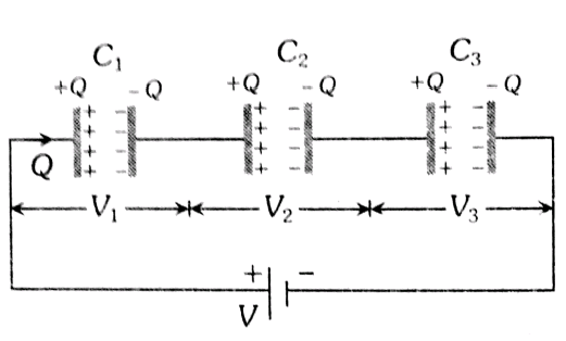
Series Combination
If capacitors are connected in such a way that we can proceed from one point to another by only one path passing through all capacitors then all these capacitors are said to be in series.

Here three capacitors are connected in series and are connected across a battery of potential difference ‘V’.
Charge: 'q' given by battery deposits at the first plate of the first capacitor. Due to induction, it attracts '–q' on the opposite plate. The pairing +ve q charges are repelled to the first plate of the Second capacitor which in turn induces -q on the opposite plate. The same action is repeated to all the capacitors and in this way, all capacitors get q charge. As a result; the charge given by battery q, every capacitor gets charge q.
Potential difference: V is the sum of potentials across all capacitors. Therefore
$\begin{gathered}V=v_1+v_2+v_3 \\ v_1=\frac{q_1}{c_1}, v_2=\frac{q_2}{c_2}, v_3=\frac{q_3}{c_3}\end{gathered}$
Equivalence equation: The equivalent capacitance for the combination of capacitance in series can be calculated as $C_e=\frac{q}{V}$.
Or,
$\begin{aligned} 1 / \mathrm{C}_{\mathrm{e}} & =\mathrm{V} / \mathrm{q} \\ & =\left(\mathrm{v}_1+\mathrm{v}_2+\mathrm{v}_3\right) / \mathrm{q} \\ & =\mathrm{v}_1 / \mathrm{q}+\mathrm{v}_2 / \mathrm{q}+\mathrm{v}_3 / \mathrm{q} \\ 1 / \mathrm{C}_{\mathrm{e}} & =1 / \mathrm{C}_1+1 / \mathrm{C}_2+1 / \mathrm{C}_3\end{aligned}$
For 2 capacitor system $C=\frac{c_1 c_2}{c_1+c_2}$, and $\quad v_1=\frac{c_2}{c_1+c_2} \cdot V$
If n capacitors of capacitance 'c' are joined in series then equivalent capacitance $C_e=\frac{c}{n}$.
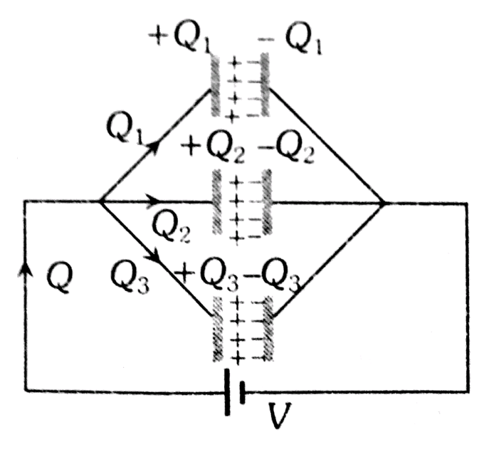
Parallel Combination
If capacitors are connected in such a way that there are many paths to go from one point to another. All these paths are parallel and the capacitance of each path is said to be connected in parallel.

Here three capacitors are connected in parallel and are connected across a battery of potential difference ‘V’.
The potential difference across each capacitor is equal and it is the same as P.D. across Battery. The charge given by the source is divided and each capacitor gets some charge. The total charge.
Therefore, each capacitor has a charge
$\mathrm{q}_1=\mathrm{C}_1 \mathrm{~V}_1, \mathrm{q}_2=\mathrm{C}_2 \mathrm{~V}_2, \mathrm{q}_3=\mathrm{C}_3 \mathrm{~V}_3$
Equivalent Capacitance: We know that when divided by v on both sides, $\frac{q}{v}=\frac{\mathrm{q}_1}{v}+\frac{\mathrm{q}_2}{v}+\frac{\mathrm{q}_3}{v}$.
Therefore the equivalence capacitance will be:
C = c1+c2+c3
The equivalent capacitance in parallel increases, and it is more than the largest in parallel. In parallel combination, V is the same, therefore $v=\frac{q_1}{c_1}=\frac{q_2}{c_2}=\frac{q_3}{c_3}$. In parallel combination $q \propto c$. The larger the capacitance larger is charge.
Charge distribution : $q_1=c_1 v, q_2=c_2 v, q_3=c_3 v$
In 2 capacitor systems charge on one capacitor $q=\frac{c_1}{c_1+c_2+\ldots} \cdot q$.
Capacitors in parallel give C = nc.
Recommended Topic Video
Solved Examples Based on Combination of Capacitors - Parallel and Series
Example 1: Figure shows a network of capacitors where the numbers indicate capacitances in micro Farad. The value of capacitance C if the equivalent capacitance between points A and B is to be 1 µF is :

1) $\frac{31}{23} \mu F$
2) $\frac{32}{23} \mu F$
3) $\frac{33}{23} \mu F$
4) $\frac{34}{23} \mu F$
Solution:
Series Grouping
$\frac{1}{C_{e q}}=\frac{1}{C_1}+\frac{1}{C_2}+\cdots$
Parallel Grouping
$\begin{aligned} & C_{e q}=C_1+C_2+\cdots \\ & C_{A B}=1 \mu f=\frac{C \times \frac{32}{9}}{C+\frac{32}{9}}=\frac{\frac{32 C}{9}}{\frac{32}{9}+C} \\ & \frac{32 C}{9}=\frac{32}{9}+C \\ & \Rightarrow C=\frac{32}{23} \mu F\end{aligned}$
Hence, the answer is the option (2).
Example 2: A capacitance of 2 µF is required in an electrical circuit across a potential difference of 1.0 kV. A large number of 1 µF capacitors are available which can withstand a potential difference of not more than 300 V. The minimum number of capacitors required to achieve this is :
1) 2
2) 16
3) 24
4) 32
Solution:
Series Grouping
$\frac{1}{C_{\mathrm{eq}}}=\frac{1}{C_1}+\frac{1}{C_2}+\cdots$
wherein
So
we need 4 capacitors to withstand 1000V
4 capacitance in series gives $C_{e q}=\frac{1}{4}$
to get $2 \mu F$ we have to connect such 8 branches in parallel
$\therefore$ Total number of capacitance $=8 \times 4=32$
Hence, the answer is the option (4).
Example 3: A $1 \mu F$ capacitor and a $2 \mu F$ capacitor are connected in parallel across a 1200-volt line. The charged capacitors are then disconnected from the line and from each other. These two capacitors are now connected to each other in parallel with terminals of unlike signs together. The charges on the capacitors will now be
1) $1800 \mu \mathrm{C}$
2) $400 \mu C$. and. $800 \mu C$
3) $800 \mu$ C..and. $400 \mu C$.
4) $800 \mu$ C..and. $800 \mu C$
Solution:
Series Grouping
$\frac{1}{C_{e q}}=\frac{1}{C_1}+\frac{1}{C_2}+\cdots$
wherein
Initially charge on capacitors can be calculated as follows
$Q_1=1 \times 1200=1200 \mu^{\prime} \mathrm{C}$ and $Q_2=2 \times 12002400 \mu_C$
Finally when the battery is disconnected and unlike plates are connected together then common potential
$V^{\prime}=\frac{Q_2-Q_1}{C_1+C_2}=\frac{2400-1200}{1+2}=400 \mathrm{~V}$

Hence, the New charge is $1^* 400=400 \mu \mathrm{C}$
And the New charge on is $C_2$ is $2^* 400=800 \mu \mathrm{C}$

Hence, the answer is the option (2).
Example 4: The figure shows a charge (q) versus voltage (V) graph for a series and parallel combination of two given capacitors. The capacitances are:

1) $40 \mu F$ and $10 \mu F$
2) $60 \mu \mathrm{F}$ and $40 \mu \mathrm{F}$
3) $50 \mu \mathrm{F}$ and $30 \mu \mathrm{F}$
4) $20 \mu \mathrm{F}$ and $30 \mu \mathrm{F}$
Solution:
For parallel
$
C_{e q}=C_1+C_2
$
So, $q_1=10\left(C_1+C_2\right)=500 \mu \mathrm{C}$
$
=>C_1+C_2=50 \mu C \text {. }
$
For series
$
\begin{aligned}
& C_{e q}=\frac{C_1 C_2}{C_1+C_2} \\
& q_2=10 C_{e q}=80
\end{aligned}
$
So,
$
\begin{aligned}
& 10 \times \frac{C_1 C_2}{C_1+C_2}=80 \\
& 10 \times \frac{C_1 C_2}{50}=80 \\
& C_1 C_2=400 \\
& C_2=10 \mu F \\
& C_1=40 \mu F
\end{aligned}
$
Hence, the answer is the option (1).
Example 5: Two capacitors C1 and C2 are charged to 120 V and 200 V respectively. It is found that by connecting them together the potential of each one can be made zero. Then :
1)9C1 = 4C2
2)5C1 = 3C2
3)3C1 = 5C2
4)3C1 + 5C2 = 0
Solution:
Parallel Grouping
$C_{\text {eq }}=C_1+C_2+\cdots$
wherein
$\begin{aligned} & 120 C_1=200 C_2 \\ & 6 C_1=10 C_2 \\ & 3 C_1=5 C_2\end{aligned}$
Hence, the answer is the option (3).
Summary
Capacitors are either connected in parallel or in series, increasing the total capacitance by means of parallel connection, since it simply involves the addition of two capacitors by their capacitances. Meanwhile, a series total capacitance actually undergoes a decrease, as the reciprocal of total capacitance is just the sum of reciprocals of individual capacitances. These combinations make the circuit extremely flexible in design, allowing the overall capacitance and voltage ratings for a specific application to be readjusted.