Force Between Two Parallel Current Carrying Conductors
The force between two parallel current-carrying conductors is a fundamental concept in electromagnetism that finds applications in both theoretical physics and practical engineering. When two wires carrying electric currents are placed close to each other, they exert a force on one another due to the interaction of their magnetic fields. If the currents flow in the same direction, the wires attract; if the currents flow in opposite directions, the wires repel. This principle is not just an academic exercise; it has real-life applications in the design of electrical devices such as transformers, electric motors, and power transmission lines. Understanding this force helps engineers optimize the efficiency and stability of these systems, ensuring that the infrastructure supporting modern technology remains robust and reliable. For instance, in power lines, managing the force between conductors can reduce energy losses and prevent potential hazards. In this article, we will study the force between parallel conductors. It is essential for both advancing scientific knowledge and improving everyday electrical technology
JEE Main 2025: Physics Formula | Study Materials | High Scoring Topics | Preparation Guide
JEE Main 2025: Syllabus | Sample Papers | Mock Tests | PYQs | Study Plan 100 Days
NEET 2025: Syllabus | High Scoring Topics | PYQs
Force Between Two Parallel Current-Carrying Infinite Wires
The force between two parallel current-carrying infinite wires is a classic problem in electromagnetism that illustrates the interaction of magnetic fields generated by electric currents. When two infinitely long, straight conductors are placed parallel to each other and carry currents, they experience a magnetic force due to the magnetic fields each wire generates. If the currents in both wires flow in the same direction, the wires attract each other. Conversely, if the currents flow in opposite directions, the wires repel each other.
Let us take two long straight conductors carrying currents $i_1$ and place them parallel to each other at a distance ‘a’ from each other as shown in the figure

Now, from the earlier concept which we have studied before, we can say that conductor 2 experiences the same magnetic field at every point along its length due to conductor 1. Because of this there will be some force acting on conductor 2 and the direction of magnetic force is indicated in the figure and it can be visualised by using the right-hand thumb rule.

Now, if we apply Ampere's circuital law on the first conductor then the magnitude of the magnetic field can be obtained as
$B_1=\frac{\mu_0 I_1}{2 \pi a}$
Then the force on a segment of length L of conductor 2 due to conductor 1 can be given as,
$F_{21}=I_2 L B_1=\frac{\mu_0 I_1 I_2}{2 \pi a} L$
Similarly, we can calculate the force exerted by the conductor 2 on the conductor 1. We see that the conductor 1 experiences the same force due to the conductor 2 but the direction of force is opposite. Thus we can say that,
$F_{21}=F_{12}$ (But the direction will be opposite.)
But if the direction of current flowing through the conductor is opposite in both the conductors then both the wires will repel each other.
Also, the magnitude of the force acting per unit length can be given as
$f_{12}=f_{21}=\frac{\mu_0 I_1 I_2}{2 \pi a}$
Recommended Topic Video
Solved Examples Based on Force between Two Parallel Current Carrying Infinite Wires
Example 1: Two wires A & B are carrying currents $I_1 \& I_2$ as shown in the figure. The separation between them is d. A third wire C carrying a current I is to be kept parallel to them at a distance x from A such that the net force acting on it is zero. The possible values of x are:
1) $x=\left(\frac{I_1}{I_1-I_2}\right) d \quad$ and $\quad x=\left(\frac{I_2}{I_1+I_2}\right) d$
2) $x=\left(\frac{I_2}{I_1+I_2}\right) d$ and $x=\left(\frac{I_2}{I_1-I_2}\right) d$
3) $x=\left(\frac{I_1}{I_1+I_2}\right) d$ and $x=\left(\frac{I_2}{I_1-I_2}\right) d$
4) $x= \pm\left(\frac{I_1}{I_1-I_2}\right) d$
Solution:

when $I_2>I_1$ ( that is wire 3 is on the left side of both 1&2)
For equilibrium,
$\begin{aligned} & F_{31}=F_{32} \\ & \frac{\mu_o I_1 I l}{2 \pi x}=\frac{\mu_o I_2 I l}{2 \pi(d+x)} \\ & \frac{d+x}{x}=\frac{I_2}{I_1} \\ & \quad x=\left(\frac{I_1}{I_2-I_1}\right) d\end{aligned}$........(I)
when $I_1>I_2$ ( that is wire 3 is on the right side of both 1&2)
$\begin{aligned} & F_{31}=F_{32} \\ & \frac{\mu_o I_1 I l}{2 \pi x}=\frac{\mu_o I_2 I l}{2 \pi(x-d)} \\ & \frac{x-d}{x}=\frac{I_2}{I_1} \\ & x=\left(\frac{-I_1}{I_2-I_1}\right) d\end{aligned}$......(II)
from (1) & (2)
$x= \pm\left(\frac{I_1 d}{I_1-I_2}\right)$
Hence the answer is the option (4).
Example 2: A rigid square loop of side a and carrying current $I_2$ is lying on a horizontal surface near a long current $I_1$ carrying wire in the same plane as shown in the figure. The net force on the loop due to the wire will be :
1) Repulsive and equal to $\frac{\mu_0 I_1 I_2}{2 \pi}$
2) Attractive and equal to $\frac{\mu_0 I_1 I_2}{3 \pi}$
3) Repulsive and equal to $\frac{\mu_0 I_1 I_2}{4 \pi}$
4) Zero
Solution:

$\begin{aligned} & F_1=\frac{\mu_0 I_1 I_2 a}{2 \pi a}=\frac{\mu_0 I_1 I_2}{2 \pi} \\ & F_2=\frac{\mu_0 I_1 I_2 a}{2 \pi .2 a}=\frac{\mu_0 I_1 I_2}{4 \pi} \\ & F_{\text {Total }}=F_1-F_2 \\ & =\frac{\mu_0 I_1 I_2}{2 \pi}-\frac{\mu_0 I_1 I_2}{4 \pi} \\ & =\frac{\mu_0 I_1 I_2}{4 \pi} \\ & \text { to right Repulsive } \\ & \end{aligned}$
Hence the answer is the option (1).
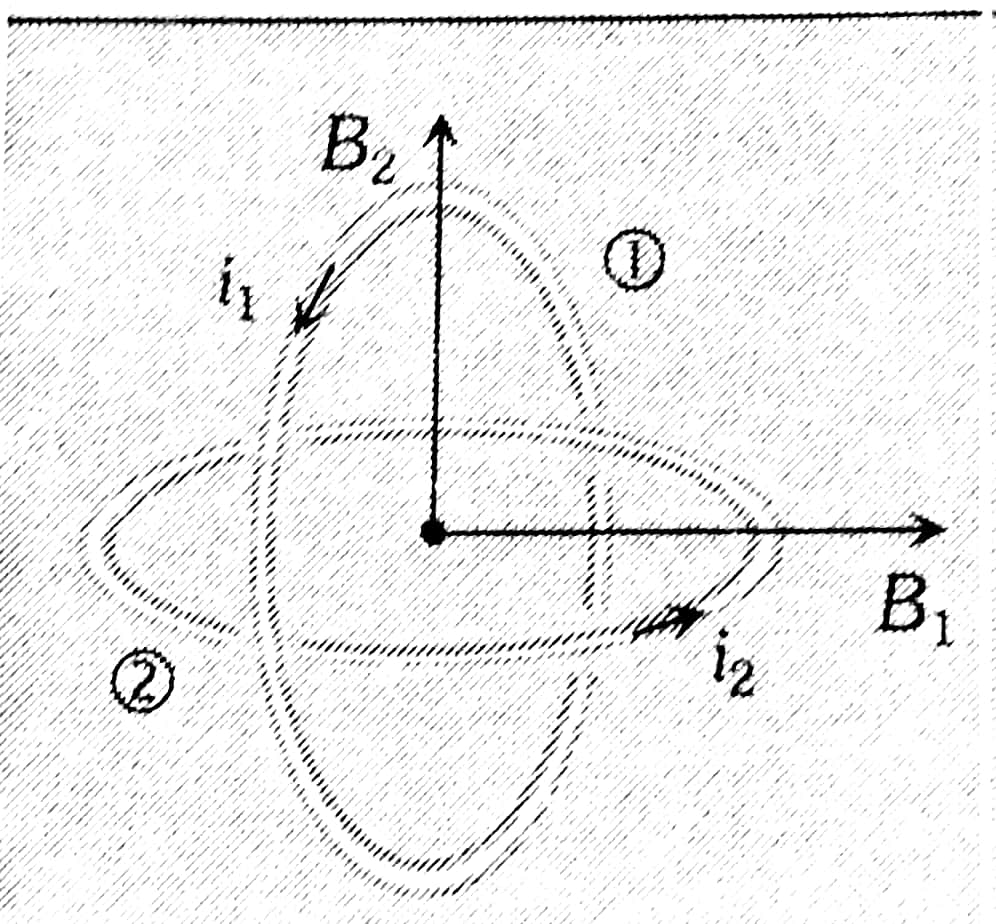
Example 3: Two concentric coils each of radius equal to $2 \pi$ cm are placed at right angles to each other. 3 ampere and 4 ampere are the currents flowing in each coil respectively. The magnetic induction in Weber/m2 at the centre of the coils will be $\left(\mu_0=4 \pi \times 10^{-7} \mathrm{~Wb} / \mathrm{A}-\mathrm{m}\right)$
1) $5 \times 10^{-5}$
2) $7 \times 10^{-5}$
3) $12 \times 10^{-5}$
4) $10^{-5}$
Solution:
Concentric loops but their planes are perpendicular to each other
$\begin{aligned} & B=\sqrt{B_1^2+B_2^2} \\ & B=\frac{\mu_o}{2 r} \sqrt{i_1^2+i_2^2}\end{aligned}$
wherein

Magnetic induction at the centre of one coil $B_1=\frac{\mu_0 i_1}{2 r}$
Similarly $\quad B_2=\frac{\mu_0 i_2}{2 r}$
$
\begin{aligned}
& \therefore \quad B^2=B_1^2+B_2^2=\left(\frac{\mu_0 i_1}{2 r}\right)^2+\left(\frac{\mu_0 i_2}{2 r}\right)^2 \\
& =\frac{\mu_0^2}{4 r^2}\left(i_1^2+i_2^2\right) \\
& \therefore \quad B=\frac{\mu_0}{2 r} \sqrt{i_1^2+i_2^2} \\
& =\frac{4 \pi \times 10^{-7}}{2 \times\left(2 \pi \times 10^{-2}\right)} \sqrt{(3)^2+(4)^2} \\
& \text { or } B=5 \times 10^{-5} \mathrm{~Wb} / \mathrm{m}^2
\end{aligned}
$
Hence the answer is the option (1).
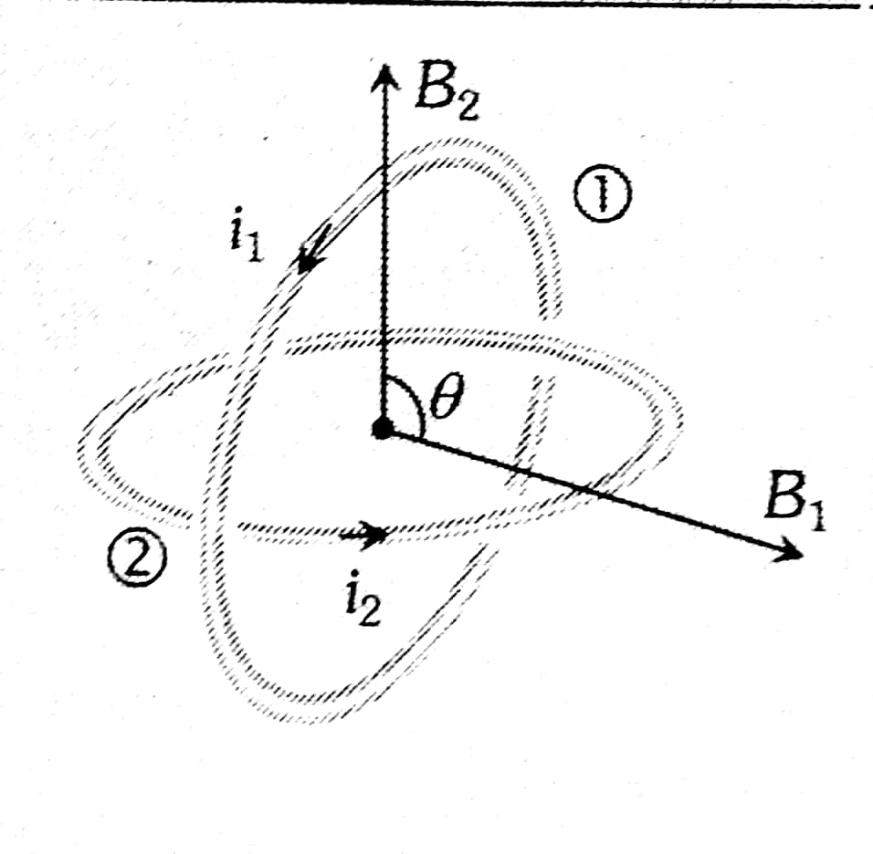
Example 4: Two similar coils are kept mutually perpendicular such that their centres coincide at the centre. Find the ratio of the magnetic field of one coil to the resultant magnetic field by both coils if the same current is flown.

1) $1: \sqrt{2}$
2) $1: 2$
3) $2: 1$
4) $\sqrt{3}: 1$
Solution:
Concentric loops but their planes are at an angle $\theta$ with each other
$B=\sqrt{B_1^2+B_2^2+2 B_1 B_2 \cos \theta}$
wherein

But,
$\begin{aligned} B_{\text {net }} & =\sqrt{2} B \\ \frac{B}{B_{\text {net }}} & =\frac{1}{\sqrt{2}}\end{aligned}$
Hence the answer is the option (1).
Example 5: Two long parallel conductors $S_1$ and $S_2$ are separated by a distance of 10 cm and carrying currents of 4 A and 2A respectively. The conductors are placed along the x-axis in the X-Y plane. There is a point P located between the conductors (as shown in the figure). A charged particle of $3 \pi$ coulomb is passing through the point P with velocity $\vec{v}=(2 \hat{\mathrm{i}}+3 \hat{\mathrm{j}}) \mathrm{m} / \mathrm{s}$; where $\hat{\mathrm{i}}_{\mathrm{i}} \& \hat{\mathrm{j}}$ represents unit vector along $x \& y$ axis respectively. The force acting on the charged particle is $4 \pi \times 10^{-u}(-x i+2 \mathrm{j}) \mathrm{N}$. The value of x is :
1) 2
2) 1
3) 3
4) -3
Solution:

Charge particle will experience a force due to the magnetic field produced by current-carrying wired using Lorentz force equation
$\vec{F}=q(\vec{v} \times \vec{B})$
To calculate the magnetic field at 'P'
$\begin{aligned} \vec{B} & =\mathrm{B}_1(-\hat{\mathrm{k}})+\mathrm{B}_2 \hat{\mathrm{k}} \\ & =\frac{\mu_0 \times 4}{2 \pi \times 4 \times 10^{-2}}(-\hat{\mathrm{k}})+\frac{\mu_0 \times 2}{2 \pi \times 6 \times 10^{-2}}(\hat{\mathrm{k}}) \\ & =\frac{\mu_0}{\pi} \times 10^2\left[\frac{-1}{2}+\frac{1}{6}\right] \hat{\mathrm{k}} \\ \vec{B} & =\frac{\mu_0}{3 \pi} \times 10^2(-\hat{\mathrm{k}}) \\ \vec{F} & =3 \pi\left[(2 \hat{\mathrm{i}}+3 \hat{\mathrm{j}}) \times\left(\frac{\mu_0}{3 \pi} \times 10^{+2}\right)(-\hat{\mathrm{k}})\right] \\ & =10^{+2} \times \mu_0[2 \hat{\mathrm{j}}-3 \hat{\mathrm{i}}] \\ & =4 \pi \times 10^{-7} \times 10^2[2 \hat{\mathrm{j}}-3 \hat{\mathrm{i}}] \\ & =4 \pi \times 10^{-5} \times[-3 \hat{\mathrm{i}}+2 \hat{\mathrm{j}}] \\ \mathrm{x} & =3\end{aligned}$
Hence the answer is the option (3).
Summary
The force between two parallel current-carrying infinite wires is a fundamental aspect of electromagnetism, driven by the interaction of their magnetic fields. If currents flow in the same direction, the wires attract; if opposite, they repel. The force per unit length between the wires can be expressed using Ampère's law. This concept is crucial for understanding practical applications such as power transmission and electric motors. Solved examples illustrate the calculation of forces and equilibrium conditions in various configurations, emphasizing the importance of this principle in both theoretical and applied physics.
Also Read
12 Sep'24 08:12 PM
12 Sep'24 01:26 PM
12 Sep'24 01:19 PM
12 Sep'24 01:07 PM
11 Sep'24 07:08 PM
08 Sep'24 12:34 PM
06 Sep'24 07:44 PM
06 Sep'24 07:43 PM
06 Sep'24 07:41 PM
06 Sep'24 07:39 PM


