Force On A Conductor Carrying Current In A Magnetic Field
When a conductor carrying an electric current is placed in a magnetic field, it experiences a force due to the interaction between the magnetic field and the electric current. This fundamental principle, described by the Lorentz force law, is a cornerstone in electromagnetism and has practical implications in various technologies. For instance, in real life, this principle is harnessed in electric motors, which are pivotal in powering countless devices from household appliances to industrial machinery. In an electric motor, a coil of wire carrying current generates a magnetic force that causes the motor to spin, converting electrical energy into mechanical energy. Another everyday application is in Maglev trains, which use magnetic levitation to achieve frictionless, high-speed travel. In this article, we will understand the force on a conductor in a magnetic field, we will unlock the potential for innovation and efficiency in transportation, energy, and beyond.
JEE Main 2025: Physics Formula | Study Materials | High Scoring Topics | Preparation Guide
JEE Main 2025: Syllabus | Sample Papers | Mock Tests | PYQs | Study Plan 100 Days
NEET 2025: Syllabus | High Scoring Topics | PYQs | Crack NEET in 2 months - Study Plan
- Magnetic Force on a Current-Carrying Conductor
- Direction of Force
- Solved Examples Based on Force on a Conductor Carrying Current In a Magnetic Field
- Summary
Magnetic Force on a Current-Carrying Conductor
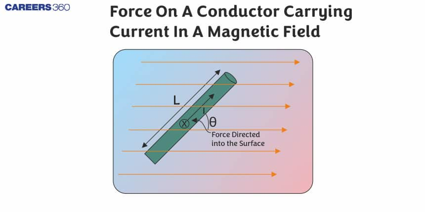
When a current-carrying conductor is placed in a magnetic field, it experiences a force known as the magnetic force. This phenomenon, governed by the principles of electromagnetism, is crucial in understanding the behaviour of electric currents in magnetic fields. According to the Lorentz force law, the force on a segment of the conductor is directly proportional to the current, the length of the conductor, and the strength of the magnetic field, and it acts perpendicular to both the direction of the current and the magnetic field.
In the case of the current-carrying conductor in a magnetic field force experienced by its small length element is $d \vec{F}=i(d \vec{l} \times \vec{B})$

For total force, we will integrate the above equation. So the total magnetic force
$\vec{F}=\int d \vec{F}=\int i(d \vec{l} \times \vec{B})$
If the magnetic field is uniform i.e., $\vec{B}$ = constant and
$\int d \vec{l}=\vec{L}=$ vector sum of all the length elements from initial to final point. Which is in accordance with the law of vector addition is equal to length vector $\bar{L}^{\prime}$ joining initial to the final point.
Then, $ \vec{F}=i\left[\int d \vec{l}\right] \times \vec{B}=i(\vec{L} \times \vec{B}) $
Direction of Force
The direction of force is perpendicular to both the length and magnetic field vector as we have discussed earlier the result of the cross product of two vectors has a direction perpendicular to both vectors. It can be found by right-hand palm rule, screw rule, right-hand thumb rule etc. Here we will discuss one important rule for this i.e., Fleming’s left-hand rule.
According to Fleming’s left-hand rule - Stretch the fore-finger, central finger and thumb left hand mutually perpendicular. Then if the fore-finger points in the direction of field $\vec{B}$ and the central in the direction of current i, the thumb will point in the direction of the force. For a better understanding, look at the image given below,

Note - If curved wire is given in the question then the length will be taken as shown in the figure

The direction of the length vector should be in the direction of the current.
Recommended Topic Video
Solved Examples Based on Force on a Conductor Carrying Current In a Magnetic Field
Example 1: A wire of length l carries current i along the x-axis in a magnetic field which is given by $\vec{B}=B_0(\hat{i}+\hat{j}+\hat{k})$. Find the magnitude of the magnetic force acting on the wire
1) $B_0 i l$
2) $\sqrt{2} B_0 i l$
3) $2 B_0 i l$
4) $\frac{1}{\sqrt{2}} B_0 i l$
Solution:
Force on a current-carrying conductor
$\begin{aligned} & d \vec{F}=i(\overrightarrow{d l} \times \vec{B}) \\ & \text { idl }=\text { current element } \\ & \vec{F}=I(\vec{l} \times \vec{B})=\vec{F}=i\left[l(\hat{i}) \times B_0(\hat{i}+\hat{j}+\hat{k})\right] \\ & \vec{F}=B_0 i l[\hat{i} \times(\hat{i}+\hat{j}+\hat{k})] \\ & \Rightarrow \vec{F}=B_0 i l(-\hat{j}+\hat{k}) \\ & \Rightarrow F=\sqrt{2} B_0 i l\end{aligned}$
Hence, the answer is the option (2).
Example 2: A wire carrying current I is tied between points P and Q and is in the shape of a circular arch of radius R due to a uniform magnetic field B (perpendicular to the plane of the paper, shown by xxx) in the vicinity of the wire. If the wire subtends an angle $2 \theta_0$ at the centre of the circle (of which it forms an arch) then the tension in the wire is :

1) IRB
2) $\frac{I B R}{\sin \theta_0}$
3) $\frac{I B R}{2 \sin \theta_0}$
4) $\frac{I B R \theta_0}{\sin \theta_0}$
Solution:
Total magnetic force
$\vec{F}=i(\vec{L} \times \vec{B})$

For the arc to be in equilibrium, $F=2 T \sin \theta_0$
$
\begin{aligned}
\Rightarrow & F=I\left(2 R \sin \theta_0\right) \times B \therefore \\
& 2 T \sin \theta_0=I 2 R \sin \theta_0 \times B \\
\Rightarrow & T=I R B
\end{aligned}
$
Hence, the answer is the option (1).
Example 3: A current of 10A is flowing in a wire of length 1.5m. A force of 15N acts on it when it is placed in a uniform magnetic field of 2T. The angle between the magnetic field and the direction of the current is
1) $30^{\circ}$
2) $45^{\circ}$
3) $60^{\circ}$
4) $90^{\circ}$
Solution:
Magnetic force for a straight conductor
$\begin{aligned} & F=B i l \sin \theta \\ & \sin \theta=\frac{15}{10 * 1.5 * 2}=\frac{1}{2} \\ & \quad \theta=30^{\circ}\end{aligned}$
Hence, the answer is the option (1).
Example 4: A current carrying a straight wire is kept along the axis of a circular loop carrying a current. The straight wire
1) will exert an Inward force on the loop
2) will exert an outward force on the loop
3) will not exert any force on the loop
4) will exert parallel force to itself.
Solution:
$\vec{F}=I(\vec{l} \times \vec{B})$
According to the question, the magnetic field due to straight wire is either parallel or antiparallel to the current flow, so the angle between the current and the magnetic field is zero degrees
$F=I d l B \sin 0=0$
So, the force experienced will be zero
Hence, the answer is the option (3).
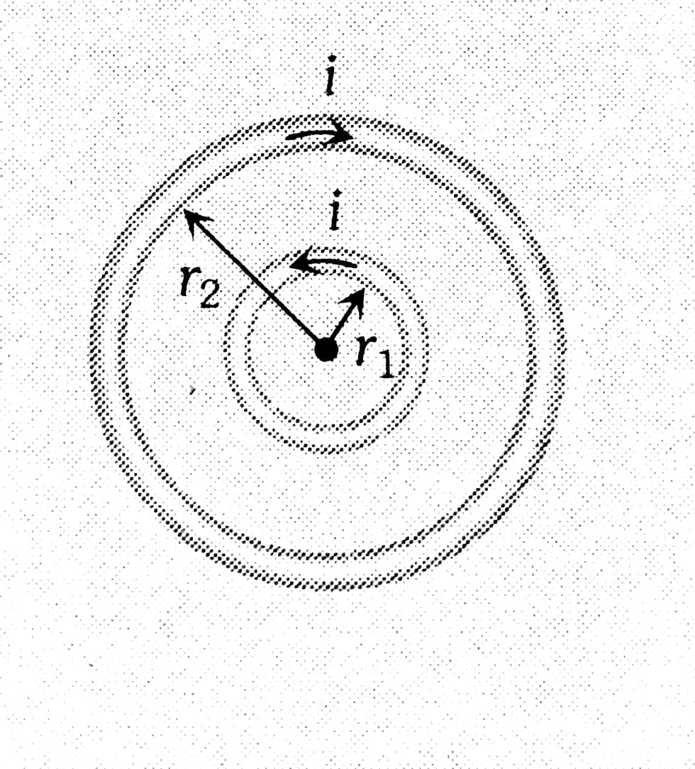
Example 5: Two concentric coplanar circular loops of $r_1$ and $r_2$ radii respectively having current I in opposite directions having n no. of turns each. Find magnetic induction at the centre of the structure.

1) $\frac{\mu_0 i n}{2 r}$
2) $\frac{\mu_0 N i}{4 \pi r}$
3) $\frac{\mu_0 i}{2}\left[\frac{1}{r_1}+\frac{1}{r_2}\right] \times n$
4) $\frac{\mu_0 i}{2}\left[\frac{1}{r_1}-\frac{1}{r_2}\right] \times n$
Solution:
Concentric co-planar circular loops carrying current
Opposite Direction
wherein
Because of the single circular coil
$
B_{\text {circ }}=\frac{\mu_0 I}{2 r} \times n
$
If current in opp direction.
So $B_{\text {net }}=\overrightarrow{B_1}-\overrightarrow{B_2}$
$
B_{n e t}=\frac{\mu_0 I}{2} \times n\left[\frac{1}{r_1}-\frac{1}{r_2}\right]
$
Hence, the answer is the option (4).
Summary
Understanding the magnetic force on a current-carrying conductor is essential for both theoretical and practical applications in electromagnetism. This principle, governed by the Lorentz force law, explains how the force is directly proportional to the current, conductor length, and magnetic field strength, and is perpendicular to both the current direction and magnetic field. Real-life applications include electric motors, which convert electrical energy into mechanical energy, and Maglev trains, which utilize magnetic levitation for high-speed travel. Various solved examples illustrate the calculation of magnetic force, demonstrating its importance in technological innovations and engineering solutions.