Hysteresis Curve
The hysteresis curve, also known as the B-H curve, represents the relationship between magnetic flux density (B) and magnetic field strength (H) in a ferromagnetic material. When a magnetic field is applied to such materials, they exhibit a lagging response in magnetization, creating a looped curve when plotted. This phenomenon, called hysteresis, shows how the material retains some magnetism even after the external magnetic field is removed.
JEE Main/NEET 2027: Physics Important Formulas for Class 10
NEET 2025: Mock Test Series | Syllabus | High Scoring Topics | PYQs
JEE Main: Study Materials | High Scoring Topics | Preparation Guide
JEE Main: Syllabus | Sample Papers | Mock Tests | PYQs
- Hysteresis
- Solved Examples Based on Hysteresis curve
- Summary
In real life, hysteresis can be observed in everyday objects like fridge magnets or electromagnets. For example, when you turn off an electromagnet, it doesn't immediately lose its magnetism, illustrating the concept of magnetic memory. Similarly, in mechanical systems like car suspensions, materials can exhibit hysteresis, as they take time to return to their original state after being stressed. Understanding the hysteresis curve is essential in designing efficient transformers, motors, and memory storage devices.
Hysteresis
It is the property of the Lagging of magnetic induction (B) behind magnetic intensity (H) in the case of the ferromagnetic substances.
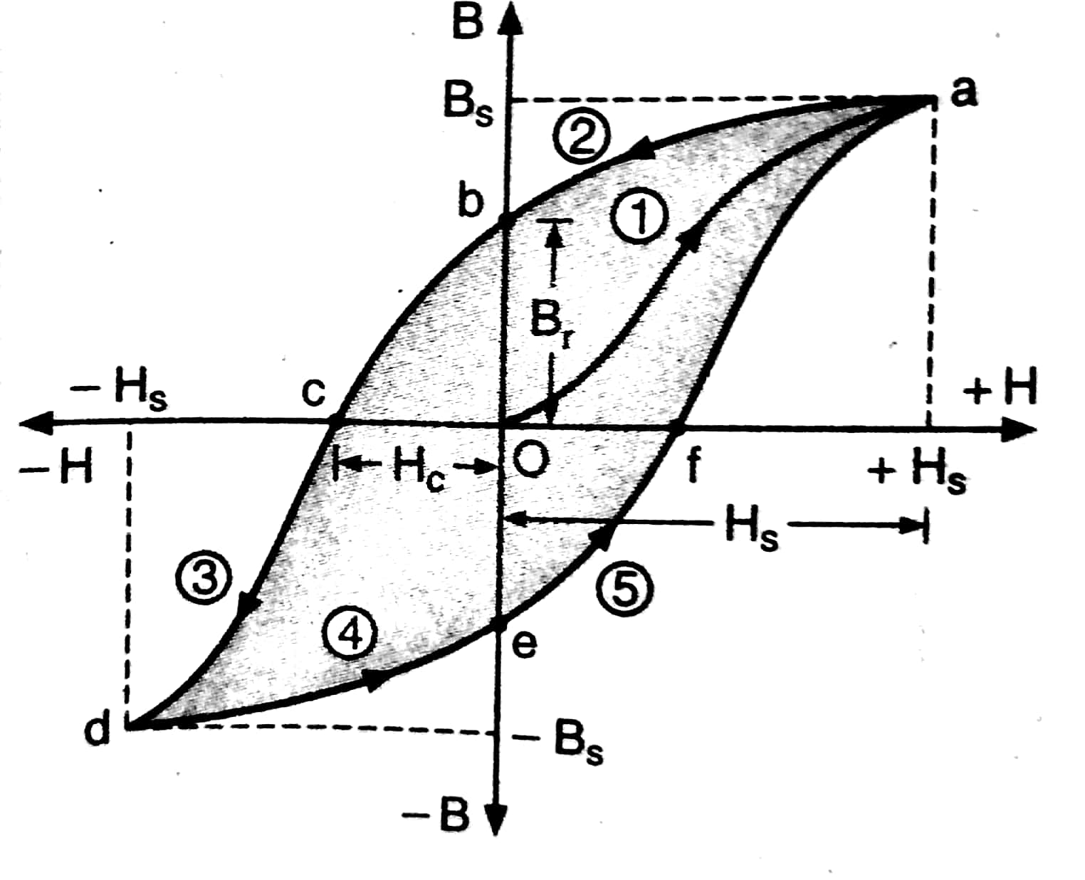
Hysteresis Curve- This is nothing but the graph of (B Vs H )or (I Vs H) as shown below.

When a non-magnetized material is placed in the long solenoid which is carrying current i as shown in the below figure.

Initially When $i=0$ then $B=0, H=0, I=0$ l.e at Point O .
Now if we increase i, it will result in an increase in B and H and 1 , till saturation point (a) I.e path 1 or Path Oa
Now we decrease H and reduce it to zero by decreasing $\mathrm{i} \Rightarrow \mathrm{I}$.e path 2 or Path ab .
So at point $\mathrm{b}, \mathrm{H}=0$ but $B \neq 0 \Rightarrow B=B_r$ where $\mathrm{B}_{\mathrm{r}}$ is called retentivity or remanence or residual magnetism.
This is happening because, For ferromagnetic materials, by removing the external magnetic field, i.e. $\mathrm{H}=0$, the magnetic moment of some domains remains aligned in the applied direction of the previous magnetising field, resulting in a residual magnetism.
Now we have to remove this residual magnetism of the material or demagnetize the material completely. For this, we will reverse the direction of the current in the solenoid.
So, the process of demagnetizing a material completely (i.e path bc) by applying the magnetizing field in a negative direction is defined as Coercivity.
So At point $c$ we have $B=0$ and $H=H_c$ where $H_c$ is called coercivity.
Coercivity signifies magnetic hardness or softness of substance:
I.,e Magnetic hard substance (steel) ——> High coercivity
Magnetic soft substance (soft iron) ——> Low coercivity.
If, after the magnetization has been reduced to zero, the value of H is further increased in the 'negative' i.e. reversed direction, the material again reaches a state of magnetic saturation, represented by point d.
Next, the current is reduced (curve de) and reversed (curve ea) then The cycle repeats itself till point a.
Recommended Topic Video
Solved Examples Based on Hysteresis curve
Example 1: The use of the study of hysteresis curve for a given material is to estimate the
1) Voltage Loss
2) Hysteresis loss
3) Current loss
4) All of the these
Solution:
Hysteresis
Lagging of magnetic induction (B) behind magnetic intensity (H)
Hysteresis loss is given by the hysteresis curve between I & H
Hence, the answer is the option(2).
Example 2: The B-H curve for a ferromagnet is shown in the figure. The ferromagnet is placed inside a long solenoid with 1000 turns/cm. The current (in mA) that should be passed in the solenoid to demagnetise the ferromagnet completely is :

1) 1
2) 2
3) 20
4) 40
Solution:
Hysteresis Curve
The graph between B and H is called hysteresis curve
wherein
Magnetic field intensity inside the material will be given by H=ni
and for demagnetization, H=100
so required current
$i=\frac{100}{1000 \text { turns } / \mathrm{cm}}=\frac{100}{10^5 \text { turns } / \mathrm{m}}=1 \mathrm{~mA}$
Hence, the answer is the option(1).
Example 3: The materials suitable for making electromagnets should have
1) high retentivity and high coercivity
2) low retentivity and low coercivity
3) high retentivity and low coercivity
4) low retentivity and high coercivity.
Solution:
Coercivity $(H)$
When $H=H_c, B=0$
i.e. Magnetising fields $(\mathrm{H})$ required to destroy the residual magnetism.
Retentivity -
When $\mathrm{H}=0$ (after having increased from 0 to $\mathrm{H}_{\mathrm{s}}$ ), $\mathrm{B}=\mathrm{B}_{\mathrm{r}}$
$B_r$ - residual magnetism, retentivity
The coercivity of a ferromagnetic material is the intensity of the applied magnetic field required to reduce the magnetization of that material to zero after the magnetization of the sample has been driven to saturation.
Materials of high retentivity and low coercivity are suitable for making electromagnets.
Hence the answer is option (2).
Example 4: Hysteresis loops for two magnetic materials A and B are given below :

These materials are used to make magnets for electric generators, transformer core and electromagnet core. Then it is proper to use :
1) A for electric generators and transformers.
2) A for electromagnets and B for electric generators.
3) A for transformers and B for electric generators.
4) B for electromagnets and transformers.
Solution:
Retentivity
When $\mathrm{H}=0$ (after having increases from 0 to $\mathrm{H}_s$ ), $B=B_r$
$B_r$ - residual magnetism, retentivity
Coercivity $(H)$ -
When $H=H_c, B=0$
wherein
i.e Magnetising fields $(\mathrm{H})$ required to destroy the residual magnetism.
Material with higher value of refentivity and coerceivity is good to make permenent magnets i.e A
Graph B is for making electro-magnets and transformers.
Hence the answer is option (4).
Example 5:

The figure gives experimentally measured B vs. H variation in a ferromagnetic material. The retentivity, co-ercivity and saturation, respectively, of the material are :
1) $1.5 \mathrm{~T}, 50 \mathrm{~A} / \mathrm{m}$ and 1.0 T
2) $1.0 \mathrm{~T}, 50 \mathrm{~A} / \mathrm{m}$ and 1.5 T
3) $1.5 \mathrm{~T}, 50 \mathrm{~A} / \mathrm{m}$ and 1.0 T
4) $150 \mathrm{~A} / \mathrm{m}, 1.0 \mathrm{~T}$ and 1.5 T
Solution:
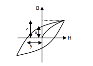
So, from the figure, we can see that the-
x = retentivity, y = coercivity, z = saturation magnetization
So, by matching with the diagram from the question and solution, option (2) is correct.
Summary
The hysteresis curve illustrates the relationship between magnetic flux density (B) and magnetic field strength (H) in ferromagnetic materials. It shows how these materials retain magnetism even after the external magnetic field is removed, demonstrating properties like retentivity (residual magnetism) and coercivity (the field needed to demagnetize). This curve is critical for understanding energy losses, hysteresis losses, and designing electromagnets, transformers, and permanent magnets with appropriate materials based on their magnetic properties.
Also Read
28 Nov'24 05:07 PM
17 Nov'24 09:58 AM
26 Sep'24 11:51 AM
26 Sep'24 11:48 AM
26 Sep'24 11:45 AM
25 Sep'24 01:20 PM
25 Sep'24 01:13 PM
25 Sep'24 01:12 PM
25 Sep'24 01:12 PM
25 Sep'24 12:58 PM