Magnetic Field Due To Circular Current Loop
A magnetic field due to a circular current loop is an essential concept in electromagnetism that helps explain how electric currents generate magnetic fields. When an electric current flows through a circular loop of wire, it produces a magnetic field around the loop, with its strength and direction determined by factors like the current’s magnitude and the radius of the loop. This concept is integral to many real-life applications, such as in electromagnets, where coiled wires create strong magnetic fields for use in machinery and electronic devices. It’s also critical in technologies like MRI scanners in medical diagnostics, where circular coils generate magnetic fields that help visualize internal body structures. The magnetic field of a current loop is foundational in the design of transformers, and motors, and even in understanding planetary magnetic fields like that of Earth. Understanding this phenomenon is key to numerous technological advancements that impact daily life.
JEE Main 2025: Physics Formula | Study Materials | High Scoring Topics | Preparation Guide
JEE Main 2025: Syllabus | Sample Papers | Mock Tests | PYQs | Study Plan 100 Days
NEET 2025: Syllabus | High Scoring Topics | PYQs | Crack NEET in 2 months - Study Plan
- Magnetic Field Due to Circular Current Loop at its Centre
- Solved Examples Based on Magnetic Field Due to Circular Current Loop
- Summary
Magnetic Field Due to Circular Current Loop at its Centre
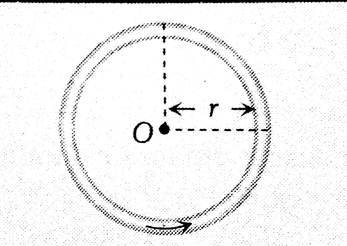
Magnetic Field due to circular coil at Centre

Consider a circular coil of radius a and carrying current I in the direction shown in Figure. Suppose the loop lies in the plane of the paper. It is desired to find the magnetic field at the centre O of the coil. Suppose the entire circular coil is divided into a large number of current elements, each of length dl.
According to Biot-Savart law, the magnetic field $d \vec{B}$ at the centre $O$ of the coil due to the current element $I \overrightarrow{d l}$ is given by,
$
\overrightarrow{\mathrm{dB}}=\frac{\mu_0 \mathrm{I}(\overrightarrow{\mathrm{di}} \times \overrightarrow{\mathrm{r}})}{4 \pi \mathrm{r}^3}
$
where $\vec{r}$ is the position vector of point $O$ from the current element.The $\overrightarrow{\mathrm{dB}}$ at the centre O is
$
\begin{aligned}
& \mathrm{dB}=\frac{\mu_0 \mathrm{Idlr} \sin \theta}{4 \pi \mathrm{r}^3} \\
& \therefore \mathrm{dB}=\frac{\mu_0 \mathrm{Id} l \sin \theta}{4 \pi \mathrm{r}^2}
\end{aligned}
$
The direction of $\overrightarrow{\mathrm{dB}}$ is perpendicular to the plane of the coil and is directed inwards. Since each current element contributes to the magnetic field in the same direction, the total magnetic field B at the centre O can be forating the above equation around the loop i.e.
$
\therefore \mathrm{B}=\int \mathrm{dB}=\int \frac{\mu_0 \mathrm{Id} l \sin \theta}{4 \pi \mathrm{r}^2}
$
For each current element, angle between \$loverrightarrow\{mathrm\{di\}\}\} and $\$ 1 \mathrm{vec}\{r\} \$ \$ is $\$ 90 \uparrow$ \circ $\} \$. Also, the distance of each current element from the centre O is a.
$
\therefore B=\frac{\mu_0 I \sin 90^{\circ}}{4 \pi \mathrm{r}^2} \int \mathrm{d} l
$
But $\int \mathrm{dl}=2 \pi \mathrm{r}=$ total length of the coil
$\therefore B=\frac{\mu_0 I}{4 \pi \mathrm{r}^2} 2 \pi \mathrm{r}$
$\therefore B=\frac{\mu_0 I}{2 \mathrm{r}}$
For N turns,
$
B_0=B_{\text {Centre }}=\frac{\mu_0}{4 \pi} \frac{2 \pi N i}{r}=\frac{\mu_0 N i}{2 r}
$
where $\mathrm{N}=$ number of turns, $\mathrm{i}=$ current and $\mathrm{r}=$ radius of a circular coil.
Magnetic Field Due to a Current-Carrying Circular arc
Case 1: Arc subtends angle theta at the centre as shown below then $B_0=\frac{\mu_0}{4 \pi} \frac{i \theta}{r}$

Proof:

Consider length element dl lying always perpendicular to $\vec{r}$.
Using the Biot-Savart law, the magnetic field produced at O is:
$
\begin{aligned}
\overrightarrow{d B} & =\frac{\mu_0}{4 \pi} \frac{I d \vec{l} \times \vec{r}}{r^3} \\
d B & =\frac{\mu_0}{4 \pi} \frac{I d l r \sin 90^{\circ}}{r^3}=\frac{\mu_0}{4 \pi} \frac{I d l}{r^2} \ldots
\end{aligned}
$
Equation (1) gives the magnitude of the field. The direction of the field is given by the right-hand rule. Thus, the direction of each of the dB is in the plane of the paper. The total field at O is
The angle subtended by element $d l$ is $d \theta$ at pt. O , therefore $d l=r d \theta$
$
\begin{aligned}
& \mathrm{B}=\int \mathrm{dB}=\frac{\mu_0}{4 \pi} I \int_0^\theta \frac{\mathrm{d} l}{\mathrm{r}^2} \\
& B=\frac{\mu_0}{4 \pi} I \int_0^\theta \frac{\mathrm{rd} \theta}{\mathrm{r}^2}=\frac{\mu_0}{4 \pi} \frac{\mathrm{I}}{\mathrm{r}} \theta \ldots \ldots
\end{aligned}
$
where the angle $\theta$ is in radians.
Case 2: Arc subtends angle $(2 \pi-\theta)$ at the centre then
$
B_0=\frac{\mu_0}{4 \pi} \cdot \frac{(2 \pi-\theta) i}{r}
$

Case 3:The magnetic field of the Semicircular arc at the centre is
$
B_0=\frac{\mu_o}{4 \pi} \frac{\pi i}{r}=\frac{\mu_o i}{4 r}
$

Case 4: Magnetic field due to three-quarter Semicircular Current-Carrying arc at the centre
$
B_0=\frac{\mu_o}{4 \pi} \frac{\left(2 \pi-\frac{\pi}{2}\right) i}{r}
$

Special Cases
1. If the Distribution of current across the diameter then $B_0=0$

2. If Current between any two points on the circumference then $B_0=0$

3. Concentric co-planar circular loops carrying the same current in the Same Direction

$
B_{\text {centre }}=\frac{\mu_o}{4 \pi}(2 \pi i)\left[\frac{1}{r_1}+\frac{1}{r_2}\right]
$
If the direction of currents is the same in concentric circles but have a different number of turns then
$
B_{\text {centre }}=\frac{\mu_o}{4 \pi}(2 \pi i)\left[\frac{n_1}{r_1}+\frac{n_2}{r_2}\right]
$
4. Concentric co-planar circular loops carrying the same current in the opposite Direction

$
B_{\text {centre }}=\frac{\mu_o}{4 \pi}(2 \pi i)\left[\frac{1}{r_1}-\frac{1}{r_2}\right]
$
If the number of turns is not the same i.e $n_1 \neq n_2$
$
B_{\text {centre }}=\frac{\mu_o}{4 \pi}(2 \pi i)\left[\frac{n_1}{r_1}-\frac{n_2}{r_2}\right]
$
5. Concentric loops but their planes are perpendicular to each other

Then $B_{\text {net }}=\sqrt{B_1^2+B_2^2}$
6. Concentric loops but their planes are at an angle $\theta$ with each other

$B_{n e t}=\sqrt{B_1^2+B_2^2+2 B_1 B_2 \cos \theta}$
Recommended Topic Video
Solved Examples Based on Magnetic Field Due to Circular Current Loop
Example 1: The magnetic field due to a current carrying a circular loop of radius 3 cm at a point on the axis at a distance of 4 cm from the centre is $54 \mu T$. What will be its value (in $\mu T$ ) at the centre of the loop?
1) 250
2) 150
3) 125
4) 75
Solution:
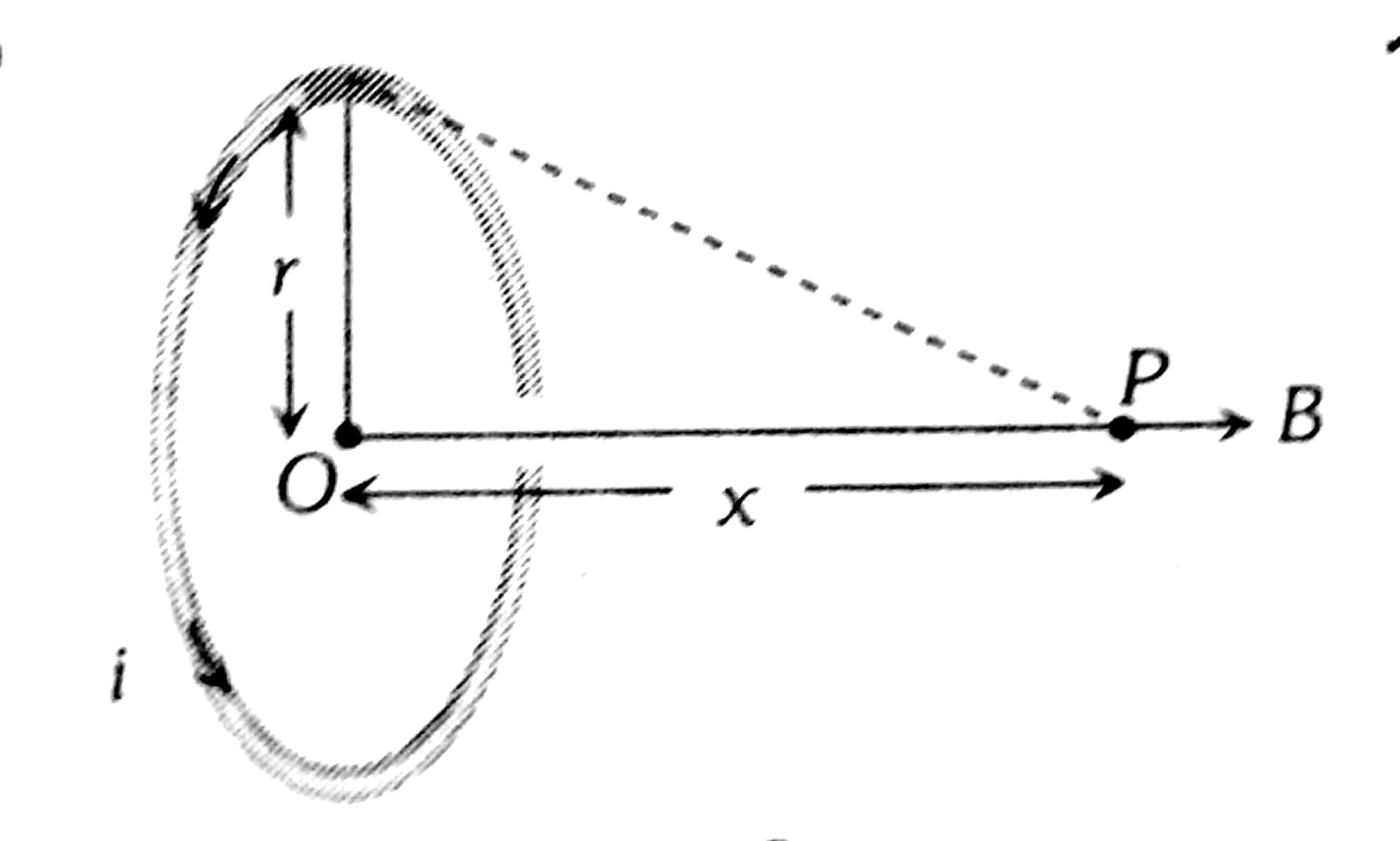
Magnetic Field at the axis due to circular current carrying wire -
$
B_{\text {axis }}=\frac{\mu_0}{4 \pi} \cdot \frac{2 \pi N i r^2}{\left(x^2+r^2\right) \frac{3}{2}}
$
wherein
N is the number of turns in the coil
Magnetic Field due to Circular Current at the centre -
$
B_{\text {centre }}=\frac{\mu_0}{4 \pi} \frac{2 \pi N i}{r}=\frac{\mu_0 N i}{2 r}
$
wherein
: Field along axis of coil $B=\frac{\mu_0 i R^2}{2\left(R^2+x^2\right)^{3 / 2}}$
At the centre of coil, $B^{\prime}=\frac{\mu_0 i}{2 R}$
$
\begin{array}{rlrl}
& \therefore & \frac{B^{\prime}}{B} & =\frac{\mu_0 i}{2 R} \times \frac{2\left(R^2+x^2\right)^{3 / 2}}{\mu_0 i R^2}=\frac{\left(R^2+x^2\right)^{3 / 2}}{R^3} \\
\therefore & B^{\prime} & =\frac{B \times\left(R^2+x^2\right)^{3 / 2}}{R^3} \\
\therefore & & =\frac{54 \times\left[(3)^2+(4)^2\right]^{3 / 2}}{(3)^3}=\frac{54 \times 125}{27}
\end{array}
$
or $\quad B^{\prime}=250 \mu T$
Hence, the answer is the Option (1).
Example 2: Directions: Questions are based on the following paragraph.
A current loop $A B C D$ is held fixed on the plane of the paper as shown in the figure. The arcs and $D A$ (radius $=a$ ) of the loop are joined by two straight wires $A B$ and $C D$. A steady current is flowing in the loop. Angle made by $A B$ and $C D$ at the origin $O$ is $30^{\circ}$. Another straight thin wire with steady current $I_1$ flowing out of the plane of the paper is kept at the origin.

Question: Due to the presence of the current $I_1$ at the origin
1) the forces on $A B$ and $D C$ are zero
2) the forces on $A D$ and $B C$ are zero
3) the magnitude of the net force on the loop is given by $\frac{I_1 I}{4 \pi} \mu_0\left[2(b-a)+\frac{\pi}{3}(a+b)\right]$
4) the magnitude of the net force on the loop is given by $\frac{\mu_0 I I_1}{24 a b}(b-a)$
Solution:
Magnetic Field due to Circular Current at the centre
If a coil of radius $r$ is carrying current $i$ then magnetic feild at a distnace $X$ from its centre is:
$
B_{\text {centre }}=\frac{\mu_0}{4 \pi} \frac{2 \pi N i}{r}=\frac{\mu_0 N i}{2 r}
$
wherein
The force on AD and BC due to current $I_1$ is zero.
This is because the directions of current element $I \overrightarrow{d I}$ and magnetic field $\vec{B}$ are parallel.
Hence, the answer is the Option (2).
Example 3: A thin ring of 10 cm radius carries a uniformly distributed charge. The ring rotates at a constant angular speed of $40 \pi \mathrm{rad} \mathrm{s}^{-1}$ about its axis, perpendicular to its plane. If the magnetic field at its center is $3.8 \times 10^{-9} \mathrm{~T}$, then the charge carried by the ring is close to $\left(\mu_0=4 \pi \times 10^{-7} N / A^2\right)$.
1) $7 \times 10^{-6} \mathrm{C}$
2) $3 \times 10^{-5} \mathrm{C}$
3) $2 \times 10^{-6} \mathrm{C}$
4) $4 \times 10^{-5} \mathrm{C}$
Solution
The magnetic field at the centre of a current-carrying ring, $B=\frac{\mu_0 i}{2 R}$
$
\begin{aligned}
& i=\frac{q}{T} \\
& T=\frac{2 \pi}{\omega} \\
& B=\frac{\mu_0 q w}{2 R(2 \pi)} \\
& \Rightarrow q=\frac{4 \pi R B}{\mu_0 w} \\
& \Rightarrow q=3 \times 10^{-5} C
\end{aligned}
$
Hence, the answer is the Option (2).
Example 4: Consider two thin identical conducting wires covered with very thin insulating material. One of the wires is bent into a loop and produces magnetic field B1' at its centre when a current I passes through it. The second wire is bent into a coil with three identical loops adjacent to each other and produces magnetic field B2 at the centre of the loops when current I/3 passes through it. The ratio B1 : B2 is :
1) 1:1
2) 1:3
3) 1:9
4) 9:1
Solution:

Magnetic field due to the first loop, $B_1=\frac{\mu_0 I}{2 r}$
For and wire, there are three loops $(n=3)$ so the total current enclosed by the loops
$
I_{\mathrm{en}}=\frac{I}{3}+\frac{I}{3}+\frac{I}{3}=I
$
The radius of the second loop $=\mathrm{r} / 3$ because the original wires are identical. magnetic field
$
\begin{aligned}
& B_2=\frac{\mu_0 I_{e n}}{2 r / 3}=\frac{\mu_0 3 I}{2 r} \\
& \frac{B_1}{B_2}=\frac{1}{3}
\end{aligned}
$
Hence, the answer is the Option (2).
Exammple 5: At the centre of a fixed large circular coil of radius R, a much smaller circular coil of radius r is placed. The two coils are concentric and are in the same plane. The larger coil carries a current I. The smaller coil is set to rotate with a constant angular velocity ω about an axis along their common diameter. Calculate the emf induced in the smaller coil after a time t of its start of rotation.
1) $\frac{\mu_0 I}{2 R} \omega \pi r^2 \sin \omega t$
2) $\frac{\mu_0 I}{4 R} \omega \pi r^2 \sin \omega t$
3) $\frac{\mu_0 I}{4 R} \omega r^2 \sin \omega t$
4) $\frac{\mu_0 I}{2 R} \omega r^2 \sin \omega t$
Solution:
Magnetic field due to a Circular Current Carrying arc
$B=\frac{\mu_o}{4 \pi} \frac{2 \pi i}{r}=\frac{\mu_o i}{2 r}$
wherein
So At the centre of a fixed large circular coil of radius R
$
B=\frac{\mu_0 I}{2 R}
$
At time $t$ the smaller coil is rotated by $\omega t$
Angle between $\vec{B}$ and $\vec{A}=\omega t$
$
\begin{aligned}
& \therefore \phi=B A \cos \omega t=\left(\frac{\mu_0 I}{2 R}\right) \Pi r^2 \cdot \cos \omega t \\
& \therefore E M F=\left|-\frac{\mathrm{d} \phi}{\mathrm{d} t}\right|=\frac{\mu_0 I \cdot \Pi r^2 \omega}{2 R} \sin \omega t
\end{aligned}
$
Hence, the answer is the Option (1).
Summary
The magnetic field due to a circular current loop is a key concept in electromagnetism, and its strength depends on the loop’s current and radius. Using the Biot-Savart law, the magnetic field at the centre of the loop can be derived, and for loops with multiple turns, the field increases proportionally. This principle is widely applied in real-world scenarios like MRI machines, electromagnets, and transformers. Various geometries of current-carrying wires, such as arcs or loops, also contribute to different magnetic field strengths, with specific formulas for each case.
Also Read
28 Nov'24 05:07 PM
17 Nov'24 09:58 AM
26 Sep'24 11:51 AM
26 Sep'24 11:48 AM
26 Sep'24 11:45 AM
25 Sep'24 01:20 PM
25 Sep'24 01:13 PM
25 Sep'24 01:12 PM
25 Sep'24 01:12 PM
25 Sep'24 12:58 PM