

Meter Bridge
The Meter Bridge, which is probably one of the most interesting and practical of all experiments in the science of physics, lends itself to a vivid understanding of the resistance phenomenon as it works in a circuit. The Meter Bridge experiment is widely used to demonstrate Ohm's Law and to understand the Wheatstone Bridge setup and hence forms a very important element in the education of students. From this experiment, one can obtain measurements of unknown resistances toward a better understanding of how balance occurs in electrical circuits. Preparing for an examination or just wondering how electrical measurements work? Well, a Meter Bridge will give you an easy yet powerful tool to familiarise yourself with resistance and circuits.
This Story also Contains
- What is the Meter Bridge?
- What is the Principle of the Meter Bridge and Potentiometer?
- Meter Bridge Experiment
- Meter Bridge Questions and Answers
What is the Meter Bridge?
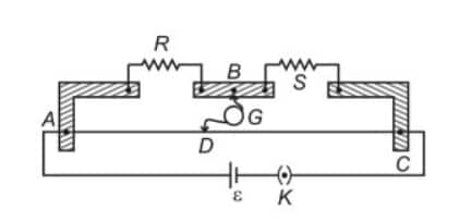
A Meter Bridge is a device used to measure unknown resistances based on the principle of Wheatstone's Bridge. It consists of a 1-meter-long wire mounted on a bridge with known resistors and unknown resistors connected in the circuit. The bridge can be balanced, and the resistance of the unknown resistor is calculated from the length ratio of the wire on either side of the jockey.
Meter Bridge Diagram
What is Another Name for a Metre Bridge?
Another name for the Meter Bridge is the Slide Bridge. In some instances, it is also referred to as a Wheatstone Bridge with respect to its principle of working, because it works on the Wheatstone Bridge method to measure unknown resistances.
What is the Principle of the Meter Bridge and Potentiometer?
The principle of the meter bridge and potentiometer is given below.
Principle of the Meter Bridge
The meter bridge works on the principle of a Wheatstone bridge. It states that when the bridge is balanced, the ratio of the resistances in the two arms of the bridge is equal to the ratio of the lengths of the wire on either side of the jockey.
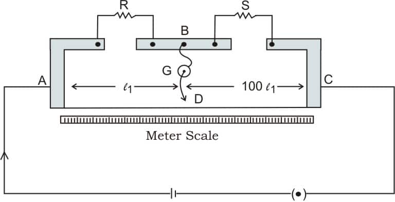
That is mathematically: $\frac{R_1}{R_2}=\frac{l_1}{l_2}$
Where:
- $\quad R_1$ and $R_2$ are the resistances in the two arms of the bridge.
- $l_1$ and $l_2$ are the lengths of the wire on either side of the jockey.
Principle of the Potentiometer
The voltage drop across a section of an element of a uniform wire is proportional to the length of that section. Thus, a potential difference-measuring instrument called the potentiometer can be used without drawing current. The concept itself is simple: for constant current, the voltage drop is proportional to the length of the wire:
$
V=k \times l
$
Where:
$V$ is the potential difference, $k$ is a constant (determined by the current and the resistance of the wire), and $l$ is the length of the wire.
Recommended Topic Video
Meter Bridge Experiment
Meter Bridge experiment provides a means of measuring unknown resistances by the construction of a Wheatstone Bridge. It consists of a 1-meter wire, which is held horizontally on a wooden or metal base, attached to both arms of the bridge with known resistors. The null point is thus achieved when the galvanometer reads zero, which means that the bridge is in a state of equilibrium.
Objective: Measurement of unknown resistance with the use of the Meter Bridge.
Apparatus:
- Meter Bridge (1-meter-long wire)
- Galvanometer
- Jockey
- Known resistor
- Unknown resistor$ R_1$ and $ R_2$
- Battery and key
- Connecting wires
Principle: The Meter Bridge is based on the principle of the Wheatstone Bridge, which states that when the bridge is in balance:
$\frac{R_1}{R_2}=\frac{l_1}{l_2}$
Procedure:
1. Setup: Connect the known resistor $R_1$ and unknown resistor $R_2$ to the meter bridge. Attach the galvanometer and jockey to the bridge.
2. Balance the Bridge: Close the key to allow current to flow. Slide the jockey along the wire until the galvanometer shows zero deflection, indicating the balance point.
3. Calculate the Unknown Resistance: Using the formula $\frac{R_1}{R_2}=\frac{l_1}{l_2}$, calculate the unknown resistance $R_2$.
Formula:
$
R_2=R_1 \times \frac{l_2}{l_1}
$
Where:
- $l_1$ and $l_2$ are the lengths measured on either side of the jockey.
Applications:
- Measurement of unknown resistances.
- Verification of Ohm's Law.
- Determining the specific resistance of a material.
Related Links-
Meter Bridge Questions and Answers
Example 1:
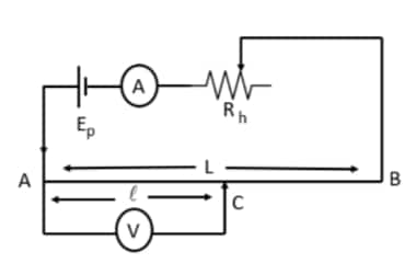
The resistance of meter bridge AB in a given figure is $4 \Omega$. With the cell of emf $\varepsilon=0.5 \mathrm{~V}$ and rheostat resistance $\mathrm{R}_{\mathrm{h}}=2 \Omega$ the null point is obtained at some point $\mathrm{J}$. When the cell is replaced by another one of emf $\varepsilon=\varepsilon_2$ the same null point $\mathrm{J}$ is found for $R_h=6 \Omega$. The emf $\varepsilon_2$ (in $\mathrm{V}$ ) is:
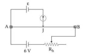
1) 0.3
2) 0.4
3) 0.6
4) 0.5
Solution:
Meter bridge
$
\frac{P}{Q}=\frac{R}{S} \Rightarrow S=\frac{(100-l)}{l} R
$
wherein
$
\begin{aligned}
& A B=l \\
& B C=(100-l)
\end{aligned}
$
For the question
When $R_h=2 \Omega$
$
\frac{d V}{d L}=\left(\frac{6}{4+2}\right) \times \frac{4}{L}
$
where $L=100 \mathrm{~cm}$
Let the null point be at $l \mathrm{~cm}$Let the null point be at l cm
$
\varepsilon_1=0.5 \mathrm{~V}=\left(\frac{6}{2+4}\right) \frac{4}{L} l ...... (1)
$
for $R_h=6 \Omega$
$
\varepsilon_2=\left(\frac{6}{4+6}\right) \frac{4}{L} \times l \ldots \ldots \ldots(2)
$
From equation (1) and (2)
$
\begin{aligned}
& \frac{0.5}{\varepsilon_2}=\frac{10}{6} \\
& \Rightarrow \varepsilon_2=0.3
\end{aligned}
$
Hence, the answer is option (1).
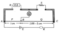
Example 2:
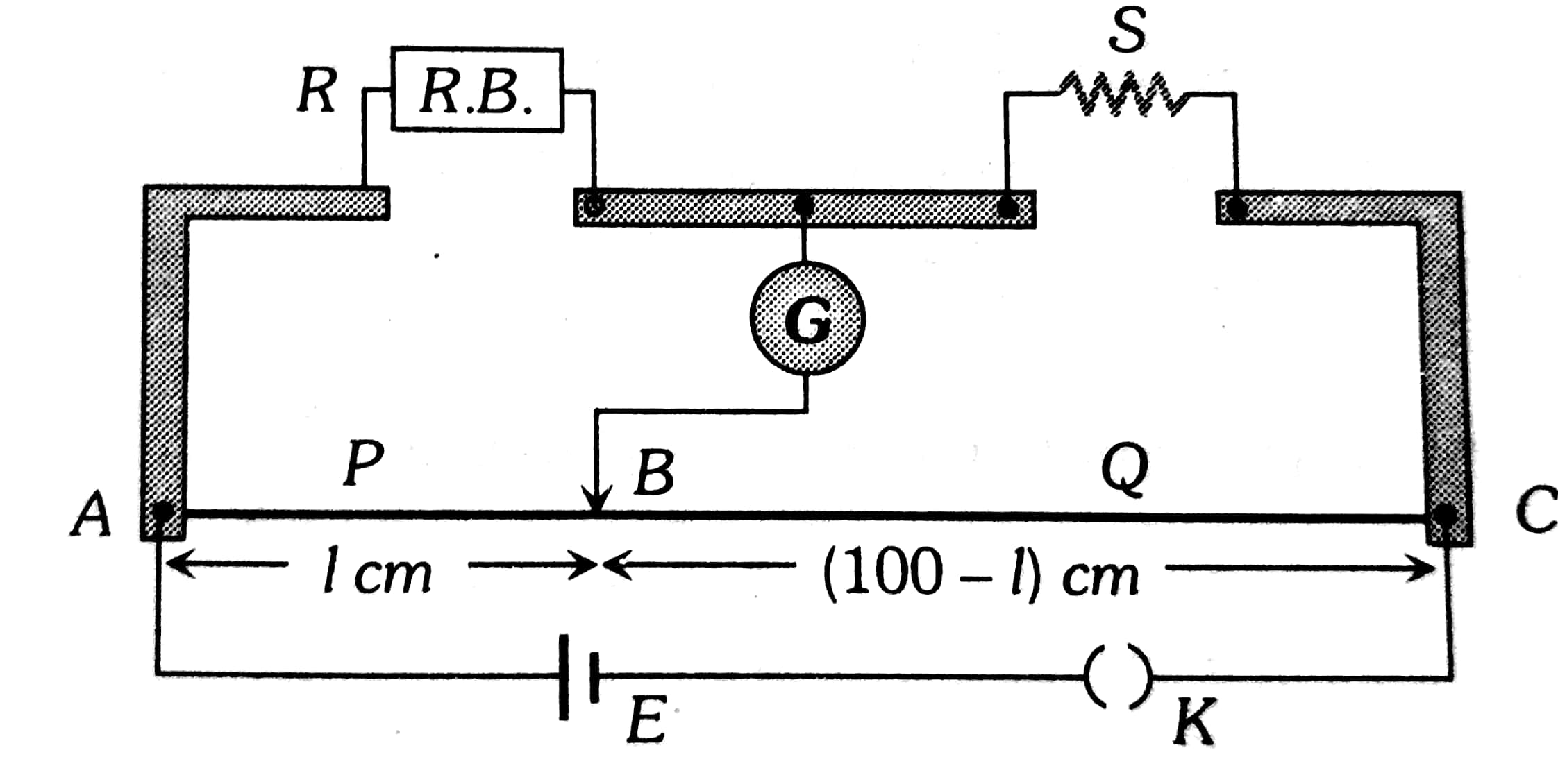
In a meter bridge experiment, S is the standard resistance, and R is the resistance wire. It is found that the balancing length is l=25 cm. If R is replaced by a wire of half length and half diameter that of R of the same material, then the balancing distance $l^{\prime}$ (in cm) will now be _____.
1) 400
2) 40
3) 20
4) 30
Solution:
$\begin{aligned}
& \frac{X}{R}=\frac{75}{25}=3 \\
& R=\frac{P^l}{A}=\frac{4 P^l}{\pi d^2} \\
& R^{\prime}=\frac{4 \rho\left(\frac{l}{2}\right)}{\pi\left(\frac{d}{2}\right)^2}=2 R \\
& \text { then, } \frac{x}{R^{\prime}}=\frac{X}{2 R}=\frac{3}{2} \\
& l=40.00 \mathrm{~cm}
\end{aligned}$
Hence, the answer is option (2).
Example 3:
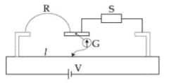
Consider a 72cm long AB as shown in the figure. The galvanometer jockey is placed at P on AB at a distance of x cm from A. The galvanometer shows zero deflection.
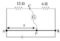
The value of x, to the nearest integer, is ____
1) 48
2) 96
3) 24
4) 72
Solution:
In Balanced conditions
$
\begin{aligned}
& \frac{12}{6}=\frac{x}{72-x} \\
& x=48 \mathrm{~cm}
\end{aligned}
$
Hence, the answer is option (1).
Example 4:
On interchanging the resistances, the balance point of a meter bridge shifts to the left by 10 cm. The resistance of their series combination is 1 kΩ. How much was the resistance (in $\Omega$ ) on the left slot before interchanging the resistances?
1) 550
2) 990
3) 505
4) 910
Solution:
Meter bridge
To find the resistance of a given wire using a meter bridge and hence determine the specific resistance of its materials
wherein
Let's say resistances are R and 1000-R
Case 1: $\frac{R}{l}=\frac{1000-R}{100-l} \quad$ .... (1)
Case II: $\frac{1000-R}{l-10}=\frac{R}{110-l}$ .................(2
Multiply both equations
$
\begin{aligned}
& \frac{R(1000-R)}{l(l-10)}=\frac{R(1000-R)}{(100-l)(110-l)} \Rightarrow l^2-10 l=11000+l^2-210 l \\
& \Rightarrow 200 l=11000 \\
& \text { or } l=55 \mathrm{~cm} \\
& \Rightarrow \frac{R}{55}=\frac{1000-R}{45}
\end{aligned}
$
or $45 R=55000-55 R$
or $R=550 \Omega$
Hence, the answer is option (1).
Example 5:
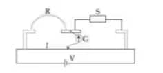
In the shown arrangement of the experiment of a meter bridge, if AC corresponding to the null deflection of the galvanometer is x, what would be its value if the radius of the wire AB is doubled?

1) $x$
2) $\frac{x}{4}$
3) $4 x$
4) $2 x$
Solution:
At null point
$\frac{R_1}{R_2}=\frac{R_3}{R_4}=\frac{x}{100-x}$
if the radius of the wire is doubled then the resistance of AC will change and the resistance of CB will also change.
But since $\frac{R_1}{R_2}$ does not change so $\frac{R_3}{R_4}$ should also not change at a null point. Therefore point C does not change.
Hence, the answer is option (1).
A slide wire bridge, also known as a meter bridge, is an instrument to compare an unknown resistance with a known level of resistance. Its principle is based on the theory of the Wheatstone Bridge, consisting of a one-meter-long uniform cross-section wire stretched on a wooden board and calibrated. On moving the contact point on this metallic conductor, one gets a balanced point for which there is no deflection on the Galvanometer.
Also Read-
