Motional Electromotive Force
Motional electromotive force (EMF) is a fascinating phenomenon that occurs when a conductor moves through a magnetic field, generating an electric current. This principle is rooted in Faraday's Law of Electromagnetic Induction, which states that a changing magnetic field can induce an electromotive force in a conductor. The concept of motional EMF is crucial in the functioning of many electrical devices and technologies we rely on daily. For instance, in a bicycle dynamo, the movement of the wheel causes a magnet to rotate near a coil of wire, generating electricity to power the bike's lights. Similarly, in large-scale power generation, turbines in power plants move through magnetic fields to produce the electricity that lights up our homes and powers our appliances. This real-world application of motional EMF underscores its importance in both everyday life and advanced technological systems, highlighting how fundamental principles of physics translate into practical innovations that drive modern society. In this article, we are going to study Motional Electromotive Force and related solved examples.
- Motional Electromotive Force
- Energy Consideration in Motional EMF
- Motional EMF Due to Rotational Motion
- Solved Examples Based on Motional Electromotive Force
- Summary
Motional Electromotive Force
Motional electromotive force (EMF) is a captivating concept in physics that emerges when a conductor moves through a magnetic field, inducing an electric current. This phenomenon is a direct consequence of Faraday's Law of Electromagnetic Induction, which explains how a changing magnetic environment can generate an electromotive force within a conductor.
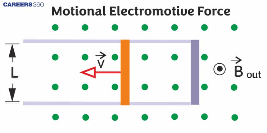
If a conducting rod of length $l$ is moving with a uniform velocity $\vec{V}$ perpendicular to the region of the uniform magnetic field $(\vec{B})$ which is directed into the plane of the paper as shown in the below figure.

Then the magnetic force on +ve charges is given by $\vec{F}_B=q(\vec{v} \times \vec{B})=e(\vec{v} \times \vec{B})$ toward side b.
Similarly, the magnetic force on -ve charges is given by $\vec{F}_B=q(\vec{v} \times \vec{B})=e(\vec{v} \times \vec{B})$ toward side a.
So positive and negative charges will accommodate at side b and side a respectively. This will create an electric field having direction from b to a. And electric force due to this field on charges will be given as $\vec{F}_E=q \vec{E}$
Applying Equilibrium condition between electric and magnetic force
$F_E=F_B \quad \Rightarrow q E=q v B \quad \Rightarrow \quad E=v B$
So Potential difference induced between the endpoints of the rod is given by
$V_{a b} \equiv V_b-V_a=E L \quad \Rightarrow V_{a b}=v B L$
This potential difference $\left(V_{a b}\right)$ is known as motional emf.
So Motional EMF is given by
$\varepsilon=B l v$
where
$B \rightarrow$ magnetic field
$l \rightarrow$ length of conducting
$v \rightarrow$ is the velocity of the rod perpendicular to a uniform magnetic field.
If the conducting PQ rod moves on two parallel conducting rails as shown in the below figure we wanted to find the motional emf of the moving rod we can calculate from two methods. we will discuss them one by one.

Method I
As magnetic flux is given by $\phi=B . A$
So, the initial flux passing through PQRS is given by $\phi=B . A=B(l . x)$
When the rod starts moving this flux will change then the change in flux is given as $\varepsilon=-\frac{d \phi}{d t}=-\frac{d}{d t}(B l x)=-B l \frac{d x}{d t}=-B l(-v)=B l v$
So the motional emf is given as $\varepsilon=B l v$
Method II
Due to the motion of the rod +ve and -ve charges of the rod will start to move towards points Q and P respectively.
Then the magnetic force on +ve charges is given by $\vec{F}_B=q(\vec{v} \times \vec{B})=e(\vec{v} \times \vec{B})$ toward Q.
Similarly, the magnetic force on -ve charges is given by $\vec{F}_B=q(\vec{v} \times \vec{B})=e(\vec{v} \times \vec{B})$ toward P.
So the work done by the magnetic force to move the +ve charge from P to Q is given by $W=\vec{F}_B \cdot l=q(\vec{v} \times \vec{B}) \cdot l=q v B l$
So potential difference across PQ is given as $\Delta V=V_{P Q}=\frac{W}{q}=B l v$
So the motional emf is given as $\varepsilon=B l v$
Energy Consideration in Motional EMF
Energy consideration in motional electromotive force (EMF) is a crucial aspect that delves into how energy is transferred and converted in systems involving moving conductors within magnetic fields. When a conductor moves through a magnetic field, work is done against the magnetic force, resulting in the generation of electrical energy. This process embodies the conservation of energy principle, where mechanical energy is converted into electrical energy.

As we learn from the above figure Motional EMF is given by
$\varepsilon=B l v$
where
$B \rightarrow$ the magnetic field
$l \rightarrow$ length of conducting
$v \rightarrow$ the velocity of the rod is perpendicular to a uniform magnetic field.
So now we want to find whether the law of conservation is applicable to the motional emf or not.
So Induced Current in the conducting rod is given as $I=\frac{\varepsilon}{r}=\frac{B l v}{r}$
Where r is the resistance of the rod
Assuming resistance of other arms (i.e. PS, SR, RQ) is negligible.
Magnetic force on the conducting rod is given as
$\begin{aligned} & F=I l B=B\left(\frac{B l v}{r}\right) l \\ & F=\frac{B^2 v l^2}{r}\end{aligned}$
The power dissipated in moving the conducting rod
$\begin{aligned} & P_{\text {mech }}=P_{\text {ext }}=F \cdot v=\left(\frac{B^2 v l^2}{r}\right) \cdot v \\ & P_{\text {mech }}=P_{\text {ext }}=\frac{B^2 l^2 v^2}{r}\end{aligned}$
Electric Power or the rate of heat dissipation across the resistance is given as
$P_E=I^2 r=\left(\frac{B l v}{r}\right)^2 \cdot r=\frac{B^2 l^2 v^2}{r}$
Since $P_{\text {mech }}=P_E$ we can say that the principle of conservation of energy is applicable for the motional emf.
General Case
Motional emf when $\vec{B}$, $\vec{V}$ and $\vec{l}$ are at some angle with each other as shown in the below figure.

Then At steady state,
$
\begin{aligned}
\text { state }, & \left|F_e\right|=\left|F_m\right| \\
& \Rightarrow F_e=-F_m \\
\Rightarrow & e \vec{E}=-\ell(\vec{V} \times \vec{B}) \\
\Rightarrow & \vec{E}=-(\vec{V} \times \vec{B})
\end{aligned}
$
$
\begin{aligned}
& \text { And Poential difference }=d v=-\vec{E} \cdot \overrightarrow{d l} \\
& \Rightarrow d v=\int(\vec{V} \times \vec{B}) \cdot \overrightarrow{d l} \\
& \Rightarrow \Delta v=(\vec{V} \times \vec{B}) \cdot \vec{l} \\
& \Rightarrow \varepsilon=(\vec{V} \times \vec{B}) \cdot \vec{l} \\
&
\end{aligned}
$
For example
- If the rod is moving make an angle $\theta$ with the direction of the magnetic field or length as shown in the below figure.

then Induced emf $\Rightarrow \varepsilon=B l V \sin \theta$
$\Delta v=$ potential difference
$B=$ Magnetic field
$V=$ velocity of the rod
Motional EMF Due to Rotational Motion
If a conducting rod PQ is rotating with angular velocity $\omega$ about its one end (Q) in a uniform magnetic field as shown in the figure below.

then $\varepsilon=\frac{1}{2} B l^2 \omega=B l^2 \pi \nu$
where
$\nu=\frac{\omega}{2 \pi}=\frac{1}{T} \rightarrow$ frequency
$T \rightarrow$ Time period
Similarly
- For the Cycle wheel rotating with an angular velocity $\omega$ about O.

$\varepsilon=\frac{1}{2} B w l^2$
- For Metal Disc

$\varepsilon=\frac{1}{2} B w r^2$
Solved Examples Based on Motional Electromotive Force
Example 1: A conducting square loop of side L and resistance R moves in its plane with a uniform velocity $v$ perpendicular to one of its sides. A magnetic induction B constant in time and space, pointing perpendicular and into the plane at the loop exists everywhere with half the loop outside the field, as shown in the figure.

The induced EMF is
1) zero
2) $R v B$
3) $v B L / R$
4) $v B L$
Solution:
Motional EMF
$\varepsilon=B l v$
wherein
$B \rightarrow$ magnetic field
$l \rightarrow$ length
$v \rightarrow$ is the velocity of v perpendicular to the uniform magnetic field.
Here Induced emf across the upper and lower sides will balanced out.
No emf appears across the right side of the loop
emf, appear across left side $=B l \vartheta$
This is not EMf-induced in $\xi=B l \vartheta$
Hence, the answer is the option (4).
Example 2:

A square frame of side 10 cm and a long straight wire carrying current 1 A are in the plane of the paper. Starting from close to the wire, the frame moves towards the right with a constant speed of 10 ms-1 (see figure). The e.m.f induced (in $\mu V$ ) at the time the left arm of the frame is at x=10 cm from the wire is :
1) 1
2) 2
3) 0.75
4) 0.5
Solution:
In the given question, Current flowing through the wire, I = 1A Speed of the frame, v=10ms-1
Side of the square loop, l=10cm
Distance of square frame from current carrying wires x = 10 cm.
According to Biot-Savart law $B=\frac{\mu_0}{4 \pi} \frac{I d l \sin \theta}{x^2}$
$
\begin{aligned}
& B=\frac{4 \pi \times 10^{-7}}{4 \pi} \times \frac{1 \times 10^{-1}}{\left(10^{-1}\right)^2}=10^{-6} \\
& \text { Induced e.m.f. } \mathrm{e}=\mathrm{Blv}=10^{-6} \times 10^{-1} \times 10 \\
& =1 \mu V
\end{aligned}
$
Hence, the answer is the option (1).
Example 3: A conducting rod of length l=2m is moving with velocity $5 \mathrm{~ms}^{-1}$ in a constant magnetic field of strength 0.5T. The power generated by the rod is 20W. Find the resistance R of the rod.

1) $1.25 \Omega$
2) $3.04 \Omega$
3) $2.60 \Omega$
4) $2.1 \Omega$
Solution:
Electric Power
$\begin{aligned} & P=I^2 R=\left(\frac{B l v}{R}\right)^2 \cdot R \\ & P=\frac{B^2 l^2 v^2}{R} \\ & P=\frac{B^2 l^2 v^2}{R} \\ & R=\frac{B^2 l^2 v^2}{P} \\ & R=\frac{(0.5)^2 *(2)^2 *(5)^2}{20} \\ & R=1.25 \Omega\end{aligned}$
Hence, the answer is the option (1).
Example 4:

A conductor of length 1 m and resistance $0.5 \Omega$ is moving in a uniform magnetic field of intensity $5 \times 10^{-4} T$ . The velocity of the conductor is 4 m/s and is directed perpendicular to the field.
The induced current in the conductor would be
1) 4 mA
2) $4 \mu \mathrm{A}$
3) 8 mA
4) $8 \mu A$
Solution:
$\begin{aligned} & I=\frac{\varepsilon}{R}=\frac{B l v}{R} \\ & \text { Induced emf } \varepsilon=B l v \\ & \text { induced current } i=\frac{\varepsilon}{R} \\ & i=\frac{B l v}{R} \\ & i=\frac{5 \times 10^{-4} \times 1 \times 4}{0.5} \times 10 \\ & i=4 \mathrm{~mA}\end{aligned}$
Hence, the answer is the option (1).
Example 5: A conducting rod of the length of l = 2 m slides at constant velocity 'v = 5 m/s' on two parallel conducting rails, placed in a uniform and constant magnetic field B = 0.5T perpendicular to the plane of the rails as shown in the figure. Find resistance R which is connected between the two ends of the rail. If the electric power dissipated in the resistor is 20 W

1) $1 \Omega$
2) $1.25 \Omega$
3) $1.5 \Omega$
4) $1.75 \Omega$
Solution:
$\begin{aligned} & P=\frac{B^2 l^2 v^2}{R} \\ & R=\frac{B^2 l^2 v^2}{P} \\ & R=\frac{(0.5)^2 *(2)^2 *(5)^2}{20} \\ & R=1.25 \Omega\end{aligned}$
Summary
Motional electromotive force (EMF) is a phenomenon where a conductor moving through a magnetic field generates an electric current. This process is fundamental to many electrical systems, from bicycle dynamos to large-scale power plants. The motional EMF is given by $\varepsilon=\mathrm{Blv}_{\text {}}$, where B is the magnetic field strength, l is the length of the conductor, and v is its velocity. Energy considerations confirm that the mechanical work done in moving the conductor translates into electrical energy, adhering to the conservation of energy principle.
Also Read
17 Nov'24 10:07 AM
25 Sep'24 05:30 PM
25 Sep'24 02:55 PM
25 Sep'24 02:53 PM
25 Sep'24 01:31 PM
25 Sep'24 01:30 PM
25 Sep'24 01:29 PM
25 Sep'24 01:27 PM
25 Sep'24 01:26 PM
25 Sep'24 01:25 PM