

Resistors In Series And Parallel Combinations
Resistors in series and parallel combinations are fundamental configurations used to control the flow of current in electrical circuits. In a series combination, resistors are connected end-to-end, resulting in a total resistance that is the sum of the individual resistances. In contrast, resistors in a parallel combination share the same voltage, and the total resistance is reduced, calculated by the reciprocal sum of the individual resistances. These combinations are vital for designing circuits with desired resistance values, influencing current distribution and voltage drops. In everyday applications, understanding these configurations is crucial in building and troubleshooting electronic devices, such as household appliances and complex circuit boards. This article explores the principles behind series and parallel resistor combinations, their mathematical relationships, and practical examples in real-world electrical systems.
This Story also Contains
- What is a Series Grouping of Resistance?
- .
- $ R_{e q}=R_1+R_2+R_3+\cdots+R_n $ $R_{e q}={ }_{\text {Equivalent Resistance }}$ For n identical resistance: $R_{\text {eq }}=n R$ $ V^{\prime}=\frac{V}{n} $
- What is Parallel Grouping of Resistance?
- Solved Examples Based on Resistors In Series And Parallel Combinations
- $I=\frac{6}{1.5}=4 \mathrm{~A}$
- Solution:
- So,
- Summary
What is a Series Grouping of Resistance?
In this case, the Potential drop is different across each resistor and the Current is the same
![w1]() .
.
 .
.$
R_{e q}=R_1+R_2+R_3+\cdots+R_n
$
$R_{e q}={ }_{\text {Equivalent Resistance }}$
For n identical resistance: $R_{\text {eq }}=n R$
$
V^{\prime}=\frac{V}{n}
$
What is Parallel Grouping of Resistance?
In this case, the Potential is the Same across each resistor and the current is different

$
\frac{1}{R_{e q}}=\frac{1}{R_1}+\frac{1}{R_2}+\cdots+\frac{1}{R_n}
$
If two resistances are in Parallel:
$
R_{e q}=\frac{R_1 R_2}{R_1+R_2}
$
Current through any resistance:

$
i^{\prime}=i\left(\frac{\text { Resistance of opposite Branch }}{\text { total Resistance }}\right)
$
The required current of the first branch
$
i_1=i\left(\frac{R_2}{R_2+R_2}\right)
$
The required current of the second branch
$
i_2=i\left(\frac{R_1}{R_1+R_2}\right)
$
Recommended Topic Video
Solved Examples Based on Resistors In Series And Parallel Combinations
Example 1: The total current (in amperes) supplied to the circuit by the battery is

1) 4
2) 2
3) 1
4) 6
Solution:
The equivalent circuits are shown below :

$I=\frac{6}{1.5}=4 \mathrm{~A}$
Hence, the answer is option (1).
Example 2: In the figure shown, what is the current (in ampere) drawn from the battery? you are given:
$R_1=15 \Omega, R_2=10 \Omega, R_3=20 \Omega, R_4=5 \Omega, R_5=25 \Omega, R_6=30 \Omega, E=15 \mathrm{~V}$
1) 13/24
2) 7/18
3) 9/32
4) 20/3
Solution:
Series Grouping
Potential - Different
Current - Same
Parallel Grouping -
Potential - Same
Current - Different
$\begin{aligned} & I=\frac{V}{R_{\mathrm{cq}}} \\ & R_{\text {eq }}=R_1+R_6+\frac{1}{\frac{1}{R_2}+\frac{1}{R_3+R_1+R_5}} \\ & =15+30+\frac{1}{\frac{1}{10}+\frac{1}{20+5+25}} \\ & =15+30+\frac{25}{3} \\ & =\frac{135+25}{3} \\ & =\frac{160}{3} \\ & I=\frac{15}{\frac{160}{3}}=\frac{45}{160}=\frac{9}{32}\end{aligned}$
Hence, the answer is option (3).
Example 3: A 3-volt battery with negligible internal resistance is connected in a circuit as shown in the figure. The current I (in Amperes) in the circuit will be

1) 1.5
2) 1
3) 2
4) 0.33
Solution:
$\begin{aligned} & \operatorname{Req}=\frac{(3+3) \times 3}{(3+3)+3}=\frac{18}{9}=2 \Omega \\ & I=\frac{V}{R}=\frac{3}{2}=1.5 \mathrm{~A}\end{aligned}$
Example 4: The total current (in amperes) supplied to the circuit by the battery is:
1) 4
2) 2
3) 1
4) 6
Solution:
The equivalent circuits are shown below :
$I=\frac{6}{1.5}=4 \mathrm{~A}$
Hence, the answer is option (1).
Example 5: In the given circuit, an ideal voltmeter connected across the $10 \Omega$ resistance reads 2 V . The internal resistance r (in $\Omega$ ), of each cell, is :

1) 0.5
2) 1
3) 1.5
4) 0
Solution:
In series Grouping
$
R_{c q}=R_1+R_2+R_3+\cdots+R_n
$
wherein
$R_{c q}-$ Equivalent Resistance
In parallel Grouping
$
\frac{1}{R_{c q}}=\frac{1}{R_1}+\frac{1}{R_2}+\cdots+\frac{1}{R_n}
$
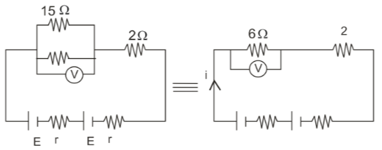
So,
$\begin{aligned} \mathrm{V} & =6 \times \mathrm{i}=2 \\ i & =\frac{1}{3} A \\ i & =\frac{2 E}{2 r+2+6} \\ & =\frac{2 \times 1.5}{2 r+8} \\ & =\frac{1}{3} \\ \Rightarrow & \Rightarrow 9=2 r+8 \\ \Rightarrow & \Rightarrow r=0.5 \Omega\end{aligned}$
Summary
As per a series combination, resistors are linked from one end to the next; the overall resistance is the sum of all individual resistances hence equal currents flowing through them with a similar voltage drop across. In the case of a parallel combination, on the other hand, resistors are connected using two common points; one can see that total resistance is always less than any one of the individual resistors leading to the same voltage drop across.
