Series LCR Circuit
A Series LCR Circuit consists of an inductor (L), capacitor (C), and resistor (R) connected in series with an alternating current (AC) source. This circuit is fundamental in understanding AC circuit behaviour, particularly resonance, where the inductive and capacitive reactances cancel each other out, resulting in a purely resistive circuit. In real life, series LCR circuits are widely used in various applications such as radio receivers and filters, where they help in tuning to specific frequencies and eliminating unwanted signals. In this article, we will explore the principles of series LCR circuits, we gain insights into how electronic devices manage signal processing and energy transfer efficiently.
JEE Main/NEET 2027: Physics Important Formulas for Class 10
NEET 2025: Mock Test Series | Syllabus | High Scoring Topics | PYQs
JEE Main: Study Materials | High Scoring Topics | Preparation Guide
JEE Main: Syllabus | Sample Papers | Mock Tests | PYQs
- Series LCR Circuit
- Solved Examples Based on Series LCR Circuit
- Summary
Series LCR Circuit
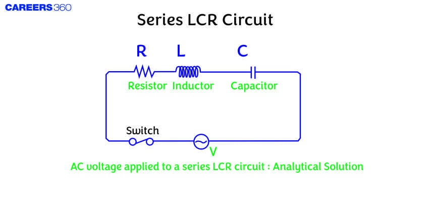
A Series LCR Circuit consists of an inductor (L), a capacitor (C), and a resistor (R) connected in series with an alternating current (AC) source. The behaviour of this circuit is governed by the interplay of inductive reactance (XL), capacitive reactance (XC), and resistance (R), which together determine the overall impedance (Z) of the circuit.
The Figure given above shows a circuit containing a capacitor, resistor and inductor connected in series through an alternating/sinusoidal voltage source.
As they are in series the same amount of current will flow in all three circuit components and for the voltage, the vector sum of potential drop across each component would be equal to the applied voltage.
Let 'i' be the amount of current in the circuit at any time and VL, VC and VR the potential drop across L, C and R respectively then
By all these, we can draw a phasor diagram as shown below

One thing that should be noticed is that we have assumed that VL is greater than VC which makes i lag behind V. If VC > VL then I lead V. So as per our assumption, their resultant will be (VL -VC). So, from the above phasor diagram V will represent the resultant of vectors VR and (VL -VC). So the equation becomes
where,
Here, Z is called the Impedance of this circuit.
Now come to the phase angle. The phase angle for this case is given as
Now from the equation of the phase angle, three cases will arise. These three cases are
(i) When,
(ii) When
(iii) When
Recommended Topic Video
Solved Examples Based on Series LCR Circuit
Example 1: Current in resistance is 1 A, then:

1)
2) The impedance of the network is
3) The power factor of the given circuit is 0.6 lagging (current is lagging)
4) All of the above
Solution:
so this is a lagging nature.
Hence, the answer is the option (4).
Example 2: Which of the following statements is correct regarding the AC circuit shown in the adjacent figure?

1) The RMS value of current through the circuit is
2) The phase difference between source emf and current is
3) The average power dissipated in the circuit is 500 W
4) None of the above
Solution:
The phase difference will be zero.
Hence, the answer is the option (4).
Example 3: An inductor L, a capacitor of
1) 2.00 H
2) 0.51 H
3) 1.5 H
4) 0.99 H
Solution:
In an L-C-R circuit, the current and the voltage are in phase
or
Hence, the answer is the option (2).
Example 4: An L-C-R series circuit consists of a resistance of
1) 0.1 H
2) 0.01 H
3) 0.2 H
4) 0.02 H
Solution:
Angular velocity,
Further,
So, put values in eq. (i), we get
Hence, the answer is the option (1).
Example 5: In the series L-C-R circuit, the voltmeter and ammeter readings are:

1) V = 100 V, I = 2 A
2) V = 100 V, I = 5 A
3) V = 1000 V, I = 2A
4) V = 3000 V, I = 1 A
Solution:
Hence, the answer is the option (1).
Summary
A Series LCR Circuit, composed of an inductor (L), capacitor (C), and resistor (R), connected in series with an AC source, demonstrates critical principles of AC circuit behaviour. At resonance, the inductive and capacitive reactances cancel each other, resulting in a purely resistive circuit. This phenomenon is essential in various applications, such as tuning radio frequencies and filtering signals. By understanding the impedance and phase angles of series LCR circuits, we gain insights into efficient signal processing and energy management in electronic devices.
Also Read
17 Nov'24 10:07 AM
25 Sep'24 05:30 PM
25 Sep'24 02:55 PM
25 Sep'24 02:53 PM
25 Sep'24 01:31 PM
25 Sep'24 01:30 PM
25 Sep'24 01:29 PM
25 Sep'24 01:27 PM
25 Sep'24 01:26 PM
25 Sep'24 01:25 PM