

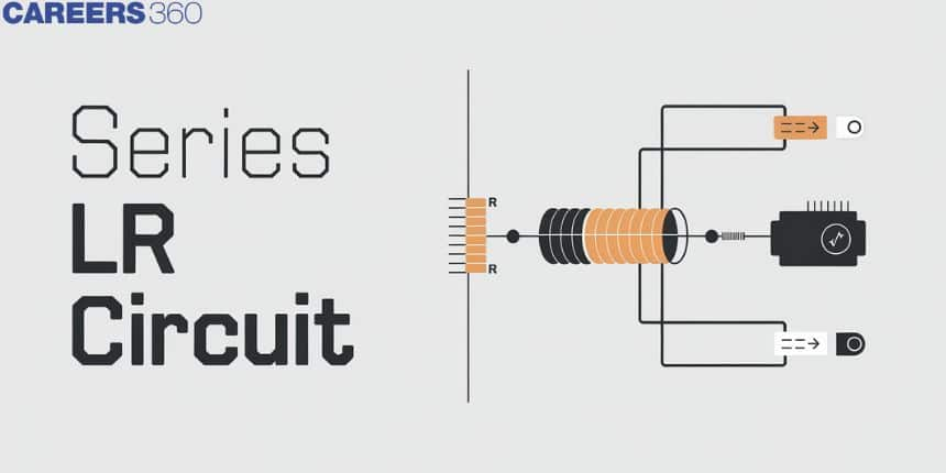
Series LR Circuit
A Series LR Circuit, consisting of an inductor (L) and a resistor (R) connected in series, is a fundamental electrical circuit used to study the behaviour of current and voltage over time. This type of circuit is essential for understanding the transient response and steady-state behaviour of inductive loads. In real life, series LR circuits are widely used in applications such as tuning radio frequencies, filtering signals in electronic devices, and controlling the speed of motors in industrial machinery. By analyzing series LR circuits, engineers can design and optimize various electronic and electrical systems for better performance and efficiency.
This Story also Contains
- Series LR Circuit
- Important Terms
- Solved Examples Based on Series LR Circuit
- Example 1: Calculate the Reactance in the given circuit
- Summary
Series LR Circuit
A Series LR Circuit consists of an inductor (L) and a resistor (R) connected in series within an electrical circuit. This combination is fundamental in analyzing how current and voltage change over time in inductive loads. In practical applications, series LR circuits are essential in various technologies such as radio frequency tuning, signal filtering in electronic devices, and controlling motor speeds in industrial equipment.
The above figure shows that the pure inductor of inductance L is connected in series with a resistor of resistance R through sinusoidal voltage, which is given by $V=V_0 \sin (\omega t+\varphi)$.
The alternating current I, which is flowing in the circuit gives rise to voltage drop VR across the resistor and voltage drop VL across the coil. As we have studied in the previous concept the voltage drop VR across R would be in phase with the current but the voltage drop across the inductor will lead the current by a phase factor $\pi / 2$.
So, the voltage drop across R is $V_R=I R$
The voltage drop across the inductor L is $\mathrm{V}_{\mathrm{L}}=\mathrm{I}(\omega \mathrm{L})$
Where I is the value of current in the circuit at a given instant of time
So, the voltage phasor diagram is

In the above figure, we have taken current as a reference quantity because the same amount of current flows through both components. Thus from the phasor diagram
$
\begin{aligned}
V & =\sqrt{V_R^2+V_L^2} \\
& =I \sqrt{R^2+\omega^2 L^2} \\
& =I Z
\end{aligned}
$
where
$
Z=\left(R^2+\omega^2 L^2\right)^{1 / 2}
$
Here, Z is known as the Impedance of the circuit.
By using the formula of impedance we can write that
$I=\frac{V_0 \sin (\omega t-\phi)}{Z}$
This is current in the steady state which lags behind applied voltage by an angle φ.
From here and the above figure, we can see that
$\tan \varphi=\frac{\omega L}{R}=\frac{X_L}{R}$
Important Terms
1. Power Factor
The power factor in an electrical system is a measure of how effectively the electrical power is being used. It is defined as the ratio of real power, which performs useful work, to apparent power, which is the product of the current and voltage in the circuit. A power factor close to 1 indicates efficient utilization of electrical power, while a lower power factor signifies inefficiencies, often due to reactive power in inductive or capacitive loads.
$
\cos \phi=\frac{R}{Z}
$
$R \rightarrow$ resistance
$
Z \rightarrow \text { impedance }
$
2. Inductive susceptance ($S_{L}$)
Inductive susceptance is a concept used in AC circuit analysis to describe the ease with which an AC circuit allows the flow of alternating current through an inductor. It is the imaginary component of admittance, which is the inverse of impedance. It is the reciprocal of reactance.
$S_L=\frac{1}{X_L}=\frac{1}{2 \pi \nu L}$
Recommended Topic Video
Solved Examples Based on Series LR Circuit
Example 1: Calculate the Reactance in the given circuit

1) $\pi$
2) $2 \pi$
3) $3 \pi$
4) $4 \pi$
Solution:
Inductive reactance XL
Opposition offered by inductive circuit.
wherein
$\begin{aligned} X_L & =\omega L=2 \pi \nu L \\ \nu_{d c} & =0 \quad X_L=0 \\ X_L & =2 * 50 * 10 * 10^{-3} * \pi \\ & =1000 * 10^{-3} * \pi \\ X_L & =\pi \Omega\end{aligned}$
Hence, the answer is the option (1).
Example 2: The susceptance of a circuit is
1) $\frac{1}{R}$
2) $\frac{1}{Z}$
3) $\frac{1}{X}$
4) None
Solution:
Susceptance is a measure of how easy it is for alternating current to pass through a capacitance or an inductance. Susceptance is the imaginary part of admittance, whose real part is conductance, which is the inverse of resistance. So conductance, Susceptance, or Admittance, all have the same unit ohm-1
Susceptance (S) - The reciprocal of reactance.
$S=\frac{1}{X}$
Hence, the answer is the option (3).
Example 3: Calculate the susceptance (S) in a given circuit

1) $\frac{1}{\pi}$
2) $\frac{2}{-\pi}$
3) $\pi$
4) $2 \pi$
Solution:
Inductive susceptance SL
$
S_L=\frac{1}{X_L}=\frac{1}{2 \pi \nu L}
$
Susceptance in the given circuit
$
\begin{aligned}
S & =\frac{1}{X_L}=\frac{1}{\omega L} \\
& =\frac{1}{2 \pi \times 50 \times 10^{-2}}=\frac{1}{\pi}
\end{aligned}
$
Hence, the answer is the option (1).
Example 4: Calculate the power factor for a given circuit

1) 0.012
2) 0.24
3) 0.028
4) 0.16
Solution:
Power factor
$
\cos \phi=\frac{R}{Z}
$
wherein
$R \rightarrow$ resistance
$Z \rightarrow$ impedance
Power factor,
$
\cos \phi=\frac{R}{Z}
$
In the given circuit
$
\begin{aligned}
& R=0.1 \Omega \\
& Z=\sqrt{R^2+\left(X_L-X_C\right)^2} \\
& X_L=\omega L=(2 \pi \times 50) \times 10^{-2}=\pi \\
& X_C=\frac{1}{\omega C}=\frac{1}{100 \pi \times 10^{-2}}=\frac{1}{\pi} \\
& Z=\sqrt{(0.1)^2+\left(\pi-\frac{1}{\pi}\right)^2}=8 \Omega
\end{aligned}
$
$\Rightarrow \cos \phi=\frac{0.1}{8}=0.012$
Hence, the answer is the option (1).
Example 5: Given fig satisfies which of the following electrical circuits?
![]()
1) Inductive Circuit
2) Capacitive Circuit
3) Resistive Circuit
4) None
Solution:
Phasor diagram
Both are on the same plane
wherein
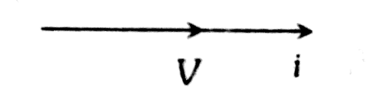
This shows that the phase difference between V and i is 0.
This is the case only for resistive circuits.
Hence, the answer is the option (3).
Summary
A Series LR Circuit, consisting of an inductor and a resistor connected in series, is essential for understanding the transient and steady-state behaviour of inductive loads. This circuit is widely used in practical applications like tuning radio frequencies, filtering signals, and controlling motor speeds. Key concepts include inductive reactance, impedance, power factor, and inductive susceptance. By analyzing these components, engineers can design and optimize various electronic and electrical systems for improved performance and efficiency.
