

Young's Double Slit Experiment
Young's Double Slit Experiment is a cornerstone of quantum physics that elegantly demonstrates the wave-particle duality of light. Conducted by Thomas Young in 1801, the experiment involves shining a coherent light source through two closely spaced slits and observing the resulting pattern on a screen. Instead of forming two distinct lines, as expected for particles, the light creates an intricate pattern of bright and dark fringes, indicating interference—a property characteristic of waves. This surprising outcome challenges our intuitive understanding of nature, showing that particles like photons can exhibit both particle-like and wave-like behaviours. In real life, this experiment's principles can be seen in phenomena such as the colourful patterns in soap bubbles, the ripples created when two stones are thrown into a pond, or even in modern technology like holography and quantum computing. In this article, we will discuss the concept of Young's double-slit experiment, assumptions, and solved examples for better concept clarity.
Young's Double-Slit Experiment
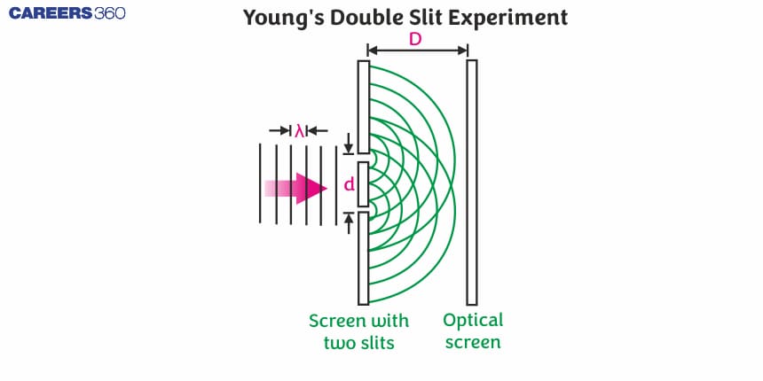
This experiment is performed by British physicist Thomas Young. He used an arrangement as shown below. In this he used a monochromatic source of light S . He made two pinholes S1 and S2 (very close to each other) on an opaque screen as shown in the figure Each source can be considered as a source of coherent light source.


So, we can see that the monochromatic light source ‘s’ kept at a considerable distance from two slits s1 and s2. The arrangement is such that the S is equidistant from S1 and S2. S1 and S2 behave as two coherent sources, as both are derived from S.
Let d be the distance between two coherent sources A and B having wavelength λ. A screen XY is placed parallel to an opaque screen at a distance D. O is a point on the screen equidistant from A and B. P is a point at a distance x from O.

From the above figure, we can see that the waves from A and B meet at P. It may be in phase or out of phase depending upon the path difference between the two waves, which we will calculate.
Draw AM perpendicular to BP
The path difference $\delta=\mathrm{BP}-\mathrm{AP}$
As we can see that, $\mathrm{AP}=\mathrm{MP}$
$$
\delta=\mathrm{BP}-\mathrm{AP}=\mathrm{BP}-\mathrm{MP}=\mathrm{BM}
$$
In right angled $\mathrm{ABM}, \quad \mathrm{BM}=\mathrm{d} \sin \theta$ if $\theta$ is small,
$$
\sin \theta=\theta
$$
The path difference $\delta=\theta \cdot d$
In right angled triangle $\mathrm{COP}, \quad \tan \theta=\mathrm{OP} / \mathrm{CO}=\mathrm{X} / \mathrm{D}$
For small values of $\theta, \tan \theta=\theta$
Thus, the path difference $\delta=\mathrm{xd} / \mathrm{D}$
So, the path difference is $=\frac{x d}{D}$
The Assumption in this Experiment
1. D> d: Since D > > d, the two light rays are assumed to be parallel.
2. d/λ >> 1: Often, d is a fraction of a millimeter and λ is a fraction of a micrometer for visible light.
For Bright Fringes
By the principle of interference, the condition for constructive interference is the path difference $=\mathrm{n} \lambda$
$$
\frac{x d}{D}=n \lambda
$$
Here, $n=0,1,2 \ldots \ldots$ indicate the order of bright fringes
So, $x=\left(\frac{n \lambda D}{d}\right)$
This equation gives the distance of the $n^{\text {th }}$ bright fringe from the point $O$.
For Dark fringes
By the principle of interference, the condition for destructive interference is the path difference = $\frac{(2 n-1) \lambda}{2}$
Here, n = 1,2,3 … indicates the order of the dark fringes.
so, $x=\frac{(2 n-1) \lambda D}{2 d}$
The above equation gives the distance of the nth dark fringe from point O.
So, we can say that the alternately dark and bright fringe will be obtained on either side of the central bright fringe.
Band Width (β)
The distance between any two consecutive bright or dark bands is called bandwidth. The bandwidth of the light source plays a crucial role in determining the clarity and visibility of the interference pattern observed on the screen.
Take the consecutive dark or bright fringe
$\begin{aligned} x_{n+1}-x_n & =\frac{(n+1) \lambda D}{d}-\frac{(n) \lambda D}{d} \\ x_{n+1}-x_n & =\frac{\lambda D}{d} \\ \beta & =\frac{\lambda D}{d}\end{aligned}$
Angular Fringe Width
Angular fringe width can be observed in the diffraction patterns of light through narrow apertures, where the angle between the bright fringes corresponds to the angular fringe width. It is an essential parameter in designing optical instruments and understanding the behaviour of light in various contexts.
$\theta=\frac{\beta}{D}=\frac{\lambda D / d}{D}=\frac{\lambda}{d}$
Solved Examples Based on Young's Double Slit Experiment
Example 1: In Young's experiment, the interfering has amplitudes in the ratio 3:2, and then ratios of amplitudes between bright and dark fringes are:
1) 5:1
2) 9:4
3) 7:1
4) 49:1
Solution:
The resultant amplitude of two waves
$A=\sqrt{A_1^2+A_2^2+2 A_1 A_2 \cos \theta}$
wherein
$A_{1}=$ amplitude of wave 1
$A_{2}=$ amplitude of wave 2
$\theta =$ phase difference
We have to obtain the ratio
$\frac{A_{\max }}{A_{\min }}=\frac{A_1+A_2}{A_1-A_2}$
and also the corresponding ratio of intensities
$\frac{I_{\max }}{I_{\min }}=\frac{\left(A_1+A_2\right)^2}{\left(A_1-A_2\right)^2}$
but $\frac{A_1}{A_2}=\frac{3}{2}$
By correspond and divide
$\frac{A_1+A_2}{A_1-A_2}=\frac{3+2}{3-2}=5$
Hence,
$\frac{A_{\max }}{A_{\min }}=5 \quad \frac{I_{\max }}{I_{\min }}=25$
Hence, the answer is the option (1).
Example 2: In Young's double slit experiment, the path difference, at a certain point on the screen between two interfering waves is $\frac{1}{8} t h$ of the wavelength. The ratio of the intensity at this point to that at the center of a bright fringe is close to:
1)0.80
2)0.94
3)0.85
4)0.74
Solution
$$
\begin{aligned}
& \Delta x=\frac{\lambda}{8} \\
& \Delta \phi=\left(\frac{2 \pi}{\lambda}\right) \frac{\lambda}{8}=\frac{\pi}{4} \\
& I=I_1+I_2+2 \sqrt{I_1 I_2} \cos \theta
\end{aligned}
$$
Putting $I_1$ and $I_2=I_o$
we get $\Rightarrow I=I_0+I_0+2 \sqrt{I_0 I_0} \cos \phi=4 I_0 \cos ^2 \frac{\phi}{2}$
At the centre $I_c=4 I_0$
and at that point $I=4 I_o \cos ^2\left(\frac{\pi}{8}\right)=I_c \cos ^2\left(\frac{\pi}{8}\right)$
$\begin{aligned} & \frac{I}{I_c}=\cos ^2\left(\frac{\pi}{8}\right) \\ & \approx 0.85\end{aligned}$
Hence, the answer is the option (3).
Example 3: Two silts in Young’s experiment have width in the ratio 1:25. The ratio of intensity at maxima and minima in the interference pattern $\frac{I_{\max }}{I_{\min }}$ is:
1) $\frac{9}{4}$
2) $\frac{3}{2}$
3) $\frac{121}{49}$
4) $\frac{5}{1}$
Solution
Maximum amplitude & Intensity
When $\theta=0,2 \pi---2 n \pi$
wherein
$\begin{aligned} & A_{\max }=A_1+A_2 \\ & I_{\max }=\left(\sqrt{I_1}+\sqrt{I_2}\right)^2 \\ & \frac{I_1}{I_2}=\frac{1}{25} \quad \text { OR } \quad \frac{I_2}{I_1}=\frac{25}{1} \\ & \frac{I_{\max }}{I_{\min }}=\left(\frac{\sqrt{I_2}+\sqrt{I_1}}{\sqrt{I_2}-\sqrt{I_1}}\right)^2 \quad \frac{I_{\max }}{I_{\min }}=\left(\frac{\sqrt{I_2}+\sqrt{I_1}}{\sqrt{I_2}-\sqrt{I_1}}\right)^2=\left(\frac{\sqrt{\frac{I_2}{I_1}}+1}{\sqrt{I_2}}\right)^2 \\ & \frac{I_{\max }}{I_{\min }}=\left(\frac{5+1}{5-1}\right)^2=\frac{9}{4}\end{aligned}$
Hence, the answer is the option (1).
Example 4: Two monochromatic light beams of intensity 16 and 9 units are interfering. The ratio of intensities of bright and dark parts of the resultant pattern is :
1) $\frac{16}{9}$
2) $\frac{4}{3}$
3) $\frac{7}{1}$
4) $\frac{49}{1}$
Solution:
Maximum amplitude & Intensity
When $\theta=0,2 \pi---2 n \pi$
wherein
$\begin{aligned} & A_{\text {max }}=A_1+A_2 \\ & I_{\max }=\left(\sqrt{I_1}+\sqrt{I_2}\right)^2\end{aligned}$
Minimum amplitude & Intensity
$\begin{aligned} & \theta=(2 n+1) \pi \\ & A_{\min }=A_1-A_2 \\ & I_{\min }=\left(\sqrt{I_1}-\sqrt{I_2}\right)^2 \\ & \frac{I_{\max }}{I_{\min }}=\left(\frac{\sqrt{I}_1+\sqrt{I}_2}{\sqrt{I_1}-\sqrt{I_2}}\right)^2=\left(\frac{4+3}{4-3}\right)^2=49: 1\end{aligned}$
Hence, the answer is the option (4).
Example 5: In Young's double slit experiment, the ratio of the slit's width is 4:1 The ratio of the intensity of maxima to minima, close to the central fringe in the screen, will be:
1) $25: 9$
2) $9: 1$
3) $4: 1$
4) $(\sqrt{3+1})^4: 16$
Solution:
$\begin{aligned} & \frac{I_1}{I_2}=\frac{4}{1} \\ & \frac{I_{\max }}{I_{\min }}=\frac{\left(\sqrt{I_1}+\sqrt{I_2}\right)^2}{\left(\sqrt{I_1}-\sqrt{I_2}\right)^2}=\left(\frac{\sqrt{\frac{I_1}{I_2}}+1}{\sqrt{\frac{I_1}{I_2}}-1}\right)^2 \\ & \Rightarrow \frac{I_{\max }}{I_{\min }}=\left(\frac{\sqrt{4}+1}{\sqrt{4}-1}\right)^2=\left(\frac{2+1}{2-1}\right)^2=\left(\frac{3}{1}\right)^2 \\ & \Rightarrow \frac{I_{\max }}{I_{\min }}=\left(\frac{9}{1}\right)\end{aligned}$
Hence, the answer is the option (2).
Summary
Young's Double Slit Experiment, conducted by Thomas Young in 1801, demonstrates the wave-particle duality of light by showing an interference pattern when coherent light passes through two closely spaced slits. This phenomenon, which produces alternating bright and dark fringes, arises from constructive and destructive interference of waves. The experiment's principles can be observed in various real-world phenomena and have significant implications in fields like holography and quantum computing. The article discusses key concepts, assumptions, and solved examples, emphasizing the importance of parameters like fringe width and intensity ratios in understanding interference patterns.
