Faraday's Law of Electromagnetic Induction
Faraday's discovery of electromagnetic induction laid the foundation for electrical engineering. Faraday's law also describes the nature of induced electromotive force in a conductor in the presence of a magnetic field. In this article, we will discuss Micahel Farady discovery, Faraday's first law of electromagnetic induction, Faraday's second law of electromagnetic induction, derivation of Faraday's law, explanation of Faraday’s experiments, and applications of Faraday’s Law.
JEE Main/NEET 2027: Physics Important Formulas for Class 10
NEET 2025: Mock Test Series | Syllabus | High Scoring Topics | PYQs
JEE Main: Study Materials | High Scoring Topics | Preparation Guide
JEE Main: Syllabus | Sample Papers | Mock Tests | PYQs
- Michael Faraday Discovery
- Faraday's First Law of Electromagnetic Induction
- Faraday’s 2nd Law
- Derivation of Faraday's Law
- Explanation of Faraday’s Experiments
- Faraday's First Experiment
- Faraday's Second Experiment
- Faraday’s Law of Electromagnetic Induction
- Applications of Faraday’s Law

Michael Faraday Discovery
Michael Faraday FRS was an English scientist who made significant contributions to the fields of electrochemistry and electromagnetism. The principles underpinning electromagnetic induction, diamagnetism, and electrolysis were among his most important discoveries.

Michael Faraday conducted substantial research on electrolysis of electrolyte solutions and melts. He was the first scientist to describe the Laws of Electrolysis in quantitative terms. He developed two laws to explain the quantitative characteristics of electrolysis, which are today known as Faraday’s laws of electrolysis, namely the first and second laws of electrolysis.
Faraday's First Law of Electromagnetic Induction
“Whenever a conductor is put in a fluctuating magnetic field, an electromotive force is induced,” according to Faraday's first law of electromagnetic induction. A current is induced when the conductor circuit is closed, and this is known as an induced current.”
where,
Faraday’s 2nd Law
The induced emf in a coil is equal to the rate of change of flux linkage
where,
Derivation of Faraday's Law
Magnetic flux is given as
For a uniform magnetic field vector
Differentiating both sides to get the rate of change of magnetic flux
Substituting terms we get
For a coil of N turns
Explanation of Faraday’s Experiments
What is the Electromagnetic Induction Experiment, and how does it work?
The mechanism through which a current can be made to flow due to a magnetic field transition is known as electromagnetic induction.
Experiment by Michael Faraday
In 1831, Faraday observed that when the number of magnetic field lines in a circuit changes, an induced EMF is formed in the circuit, a process known as electromagnetic induction. The current runs through the circuit when it is closed, and this is known as the induced current. While the magnetic flux fluctuates, the induced EMF and electric current endure only a short time. Faraday and Henry are two examples of this type of work.
Faraday's First Experiment
- A closed circuit with an insulated wire coil.
- Also, because there is no source of EMF in the circuit, there is no deflection in the galvanometer.
- When we advance the bar magnet towards the coil while keeping the coil fixed (say), the needle of the galvanometer deflects, indicating the current pressure in the circuit.
- This deflection is only visible for the period of time that the magnet is moving. The galvanometer needle is now deflected in the other direction if we press the magnet in the opposite way.
- The deflection is now in the other direction if we move the magnet towards the coil with its south pole facing coil, suggesting that the current set in the coil is now in the opposite direction as when the north pole faces the wire.
- When the magnet is stationary and the circuit is moved away from the magnet, the galvanometer shows deflection.
- The velocity of the magnet is likewise observed to be higher, as is the deflection of the galvanometer needle.
- Faraday deduced from this experiment that moving the magnet in one direction toward the coil had the same effect as moving the coil in the opposite direction toward the magnet.

Faraday's Second Experiment
- The deflection is now in the other direction if we move the magnet towards the coil with its south pole facing coil, suggesting that the current set in the coil is now in the opposite direction as when the north pole faces the wire.
- When the magnet is stationary along with the circuit moving away from the magnet, the galvanometer shows deflection.
- The velocity of the magnet is likewise observed to be higher, as is the deflection of the galvanometer needle.
- Faraday deduced from this experiment that moving the magnet in one direction toward the coil had the same effect as moving the coil in the opposite direction toward the magnet.
|
Related Topics, |
Faraday’s Law of Electromagnetic Induction
The creation of electromotive force across electrical conductors in a changing magnetic field is called magnetic induction. Induction was discovered by Michael Faraday in 1813 as well as it was mathematically characterized as Faraday’s law of induction by James Clerk Maxwell.
Electromagnetic Induction According to Faraday’s law:
- The time rate of change of magnetic flux in the circuit equals the magnitude of the induced emf in the circuit. The induced emf can be calculated using the formula
- The negative sign indicates that the current generated in a circuit frequently flows in such a way that it opposes or causes the change.
In the case of a tightly wound N-turn coil, the flux change associated with each turn is identical. As a result, the expression for the total induced emf is -
Applications of Faraday’s Law
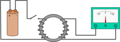
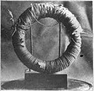
An electrical transformer is a common use of Faraday’s law. A transformer is made up of two independent coils wound around a piece of iron. The primary coil is one of two, while the secondary coil is the other. Due to Faraday’s law, this shifting field will induce a current in the secondary.

Other applications are:
- Faraday’s ring transformer
- Electric generators
- Electromagnetic brakes
- Metal Detectors
Also read:
Frequently Asked Questions (FAQs)
The Faraday is a non-measuring electric charge volume unit equivalent to about 6.02 x 10^23 electric charge carriers.
According to Faraday’s law, a fluctuating magnetic flux generates an electric field. Faraday’s law is particularly essential since it deals with the E-field-B-field relationship and recognizes that this connection necessitates flux variation over time.
Electrolysis is a technique for eliminating iron oxide that involves delivering a tiny electrical charge from a battery or battery charger through rusted metal to stimulate ion exchange while the device is submerged in an electrolyte solution.
The cathode is the negatively charged electrode created by electrolysis. In electrolysis, the positively charged electrode is known as the anode. Ions with a negative charge are travelling towards the anode.
The force in any closed circuit due to a change in the flux linkage of the circuit is called electromotive force EMF, according to Faraday’s law.
Also Read
20 Nov'24 10:41 PM
15 Nov'24 04:55 PM
14 Nov'24 02:28 PM
14 Nov'24 12:28 PM
13 Nov'24 05:30 PM
11 Nov'24 07:17 PM
24 Sep'24 10:20 PM
24 Sep'24 10:12 PM
24 Sep'24 12:07 PM
19 Sep'24 01:55 PM

