

Torque On Current Loop And Magnetic Moment Derivation
Understanding the torque on a current loop and its magnetic moment is pivotal in electromagnetism and has numerous practical applications. When an electric current flows through a loop of wire placed in a magnetic field, it experiences a torque. This phenomenon is rooted in the interaction between the magnetic field and the magnetic moment of the current loop, leading to rotational motion. The derivation of this torque provides insight into the fundamental principles governing electric motors, galvanometers, and magnetic sensors. In real life, these principles are harnessed in the operation of household appliances, electric vehicles, and various measuring instruments. This article delves into the mathematical derivation of torque on a current loop and explores its significance in technological advancements.
This Story also Contains
- Torque on a Rectangular Current Loop in a Uniform Magnetic Field
- Solved Examples Based on Torque on Current Loop and Magnetic Moment Derivation
- Summary
Torque on a Rectangular Current Loop in a Uniform Magnetic Field
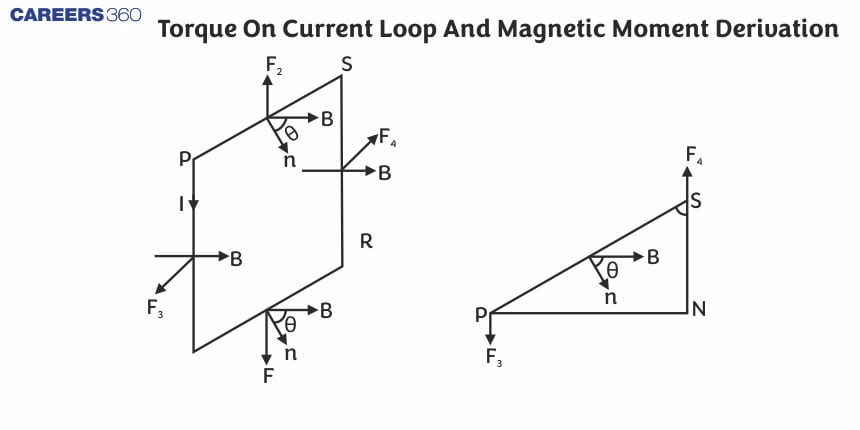
As we have studied the electric dipole in a uniform electric field it will experience a torque similarly if we place a rectangular loop carrying a steady current $i$ and placed in a uniform magnetic field experiences a torque. It does not experience a net force.
Let us consider a case when the rectangular loop is placed such that the uniform magnetic field B is in the plane of the loop. This is illustrated in the given figure. The field exerts no force on the two arms AD and BC of the loop. It is perpendicular to the arm AB of the loop and exerts a force F1 on it which is directed into the plane of the loop. Its magnitude is,
$F_1=I b B$

Similarly, it exerts a force F2 on the arm CD and F2 is directed out of the plane of the paper.
$F_2=I b B=F_1$
Thus, the net force on the loop is zero. But these two forces are acting at a distance 'a' between them. This torque on the loop is due to the pair of forces F1 and F2. The figure given below shows that the torque on the loop tends to rotate anti-clockwise. This torque is (in magnitude),

$\begin{aligned} \tau & =F_1 \frac{a}{2}+F_2 \frac{a}{2} \\ & =I b B \frac{a}{2}+I b B \frac{a}{2}=I(a b) B \\ & =I A B\end{aligned}$
where A = ab is the area of the rectangle.
Now we will discuss the case when the plane of the loop is making an angle $\theta$ with a magnetic field. In the previous case, we have considered $\theta=\frac{\pi}{2}$, but this is now a general case.

Here again, you can see that the forces on arms AB and CD are F1 and F2
$F_1=F_2=I b B$
Then the torque will be the
$\begin{aligned} \tau & =F_1 \frac{a}{2} \sin \theta+F_2 \frac{a}{2} \sin \theta \\ & =\text { Iab } B \sin \theta \\ & =I A B \sin \theta\end{aligned}$
From the above equations, we can see that the torques can be expressed as the vector product of the magnetic moment of the coil and the magnetic field. We define the magnetic moment of the current loop as,
$m=I A$
If the coil has N turns then the magnetic moment formula becomes
$m=N I A$
Its direction is defined by the direction of the Area vector.
So, the Torque equation can be written as,
$\tau=\mathbf{m} \times \mathbf{B}$
The magnitude of the magnetic moment of a current-carrying loop is
$|\vec{M}|=N i A$
i = current in the loop
N = number of turns in the loop
A = area of cross-section of the loop
Solved Examples Based on Torque on Current Loop and Magnetic Moment Derivation
Example 1: A magnetic dipole is acted upon by two magnetic fields which are inclined to each other at an angle of 750. One of the fields has a magnitude of 15 mT. The dipole attains stable equilibrium at an angle of 300 with this field. The magnitude of the other field (in mT ) is close to :
1) 11
2) 36
3) 1
4) 1060
Solution:
Torque
$
\vec{\tau}=\vec{M} \times \vec{B}(\text { where } M=N i A)
$
For stable equilibrium, the net torque acting on the dipole must be zero
$
\vec{\tau}_1+\vec{\tau}_2=0
$
or,
$
\left|\vec{\tau}_1\right|=\left|\vec{\tau}_2\right|
$
$
M B_1 \sin \theta_1=M B_2 \sin \theta_2
$
$
\begin{aligned}
& B_2=B_1 \frac{\sin \theta_1}{\sin \theta_2}=15 m T \frac{\sin 30^{\circ}}{\sin 45^0} \\
& B_2=15 m T \times \frac{1}{2} \times \sqrt{2}=10.6 \mathrm{mT}=11 \mathrm{mT}
\end{aligned}
$
Hence the answer is the option (1).
Example 2: A magnetic dipole in a constant magnetic field has :
1) maximum potential energy when the torque is maximum.
2) zero potential energy when the torque is minimum.
3) zero potential energy when the torque is maximum.
4) minimum potential energy when the torque is maximum.
Solution:
Torque
$
\begin{aligned}
& \vec{T}=\vec{M} \times \underset{B}{\vec{B}}=M=N i A \\
& \mathrm{~T}=M B \sin \theta=N B i A \sin \theta
\end{aligned}
$
wherein
M - magnetic moment
Work done by current carrying coil
$
W=M B(1-\cos \theta)
$
For maximum torque, $\theta=90^{\circ}$ this value of $\theta$ potential energy will be zero.
Hence the answer is the option (3).
Example 3: At some locations on Earth, the horizontal component of the E magnetic field is $18 \times 10^{-6} T$. At this location, a magnet of length 0.12 m and pole strength 1.8 Am is suspended from its mid-point using a thread, it makes 450 horizontal in equilibrium. To keep this needle horizontal, the vertical force that should be applied at one of its ends is:
1) $1.3 \times 10^{-5} \mathrm{~N}$
2) $6.5 \times 10^{-5} \mathrm{~N}$
3) $3.6 \times 10^{-5} \mathrm{~N}$
4) $1.8 \times 10^{-5} \mathrm{~N}$
Solution:
$\begin{aligned} & A t 45^{\circ}, \\ & \mathrm{B}_{\mathrm{H}}=\mathrm{B}_{\mathrm{V}} \\ & \frac{\mathrm{F} l}{2}=M B_{\mathrm{V}}=\mathrm{m} \times 1 \times B_{\mathrm{V}} \\ & \mathrm{F}=\frac{2 \mathrm{ml} \mathrm{B}_{\mathrm{V}}}{1}=3.6 \times 18 \times 10^{-6} \\ & \mathrm{~F}=6.5 \times 10^{-5} \mathrm{~N}\end{aligned}$
Hence, the answer is the option (2).
Example 4: A conducting circular loop of radius r carries a constant current i. It is placed in a uniform magnetic field $\vec{B}$ such that the plane is perpendicular to the magnetic field. Find the magnetic force on it
1) $\operatorname{Ir} \vec{B}$
2) $2 \pi i r \vec{B}$
3) 0
4) $\pi r i \vec{B}$
Solution:
Given a circular coil of radius r and carrying current $I$. Suppose the loop lies in the plane of the paper and uniform magnetic field B which is perpendicular to the plane Suppose the entire circular coil is divided into a large number of current elements, each of length $dl$
The force on a current-carrying conductor due to a magnetic field is given as
$d \vec{F}=i(d \vec{l} \times \vec{B})$
Using Fleming’s left-hand rule, we observe that the force is acting towards the centre.
Similarly, for every element of the circular loop, the force will act towards the centre and each force on an element of the loop will get cancelled by the force acting on the opposite side of the loop. Thus, the net force will be zero.
Force acting on a conductor with a closed loop due to a uniform magnetic field acting perpendicular to the loop is always zero.
Hence, the answer is the option (3).
Example 5: A small coil of N turns has an effective area of A and carries a current I. It is suspended in a horizontal magnetic field such that it is perpendicular to $\vec{B}$. The work done in rotating it by $180^{\circ}$ about the vertical axis is
1) NAIB
2) 2 NAIB
3) $2 \pi N A I B$
4) $4 \pi N A I B$
Solution:
Work done for rotating a magnetic dipole in a uniform magnetic field
$d W=\tau d \theta$
$W=\int \tau d \theta=\int_{\theta_1}^{\theta_2} \tau d \theta \Rightarrow W=\int_{\theta_1}^{\theta_2}(M \times B) d \theta=\int_{\theta_1}^{\theta_2}(M B \operatorname{Sin} \theta) d \theta=M B\left(\cos \Theta_1-\cos \Theta_2\right)=N I A B\left(\cos \Theta_1-\cos \Theta_2\right)$
Given the magnetic dipole rotated by $180^{\circ}$.
So work done, $W=N I A B\left(\cos \theta_1-\cos \theta_2\right)$
$
\begin{aligned}
& W=N I A B\left(\cos 0^{\circ}-\cos 180^{\circ}\right) \\
& W=2 N I A B
\end{aligned}
$
Hence, the answer is the option (2).
Summary
Understanding the torque on a current loop and its magnetic moment is fundamental to electromagnetism, with practical applications in devices like electric motors, galvanometers, and magnetic sensors. When a current-carrying loop is placed in a magnetic field, it experiences a torque due to the interaction between the field and the loop's magnetic moment. The mathematical derivation of this torque reveals its dependency on factors such as current, area, and the angle between the field and the loop, highlighting the principles used in numerous technological advancements.
