

Projection and View: Definition, Types, and Applications
A useful design skill is the ability to draw objects from a three-dimensional world onto a two-dimensional plane. The use of projections and views allows engineers, architects, designers, artists, and others to better understand, explain, and work on the concepts. These techniques are essential for producing intricate and understandable drawings that highlight the form, arrangement, and utility of spaces and objects.
This Story also Contains
- Projection: Types, Definitions and Applications
- Projection Methods: 1st and Third Angle
- Views: Types, Definitions and Applications
- Important Practice Questions from UCEED/NID
It also helps to understand the difference between projection and view for the designer to realize that his or her concept can be broadly understood in order to deliver the overall vision more effectively. Therefore, it is very important to understand and develop the skill for students preparing for design aptitude tests like as NID and UCEED.
Projection: Types, Definitions and Applications
Students can understand and learn the basics of what projections are and how can they be applied by reading this article:
What is a Projection?
Projection means to transfer three-dimensional objects onto two dimensional planes by Orthographic, Isometric and Perspective Projection Techniques. As such, each step captures relative sizes and relative positions, which is important when making technical drawing, building plans, and design drawings.
Different Types of Projections:
Different types of projections that are usually asked in design exams are given below:
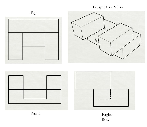
Orthographic Projection:
It includes an extension of edges of the object’s features onto perpendicular planes.
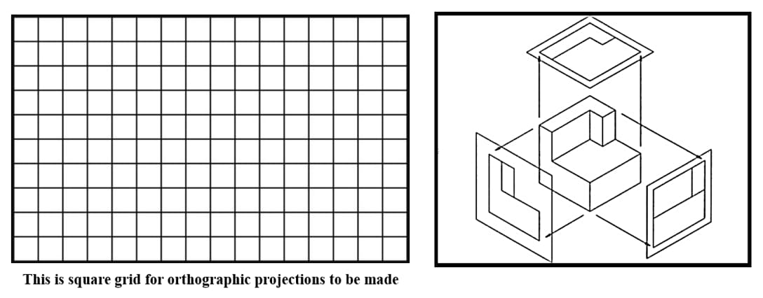
It shows different views (Front- Side) without Perspective Distortion.
Application: Standardly employed in drafting maps, structural plans and layouts, mechanical designs, architectural designs among other fields to indicate measurements as well as positions of various parts of an item.
Example - Orthographic projection can only be understood better and made more precise when different views of the form of a solid are projects as shown below.
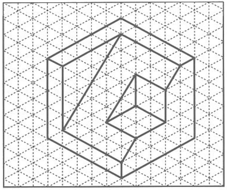
Isometric Projection and View:
Isometric projection is mapping three dimensional objects onto two dimensional plane.
The angles between the projection axes consist of 30 degrees, and all the projection axes are proportionally scaled, and thus do not distort proportions.
Application: Often applied in a technical drawing, CAD model, and other games design to provide a perception of the object and form a proper concept of the geometry of the object and its location.
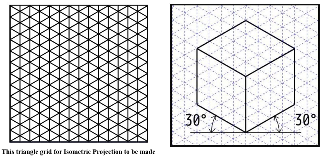
Example - Here, a solid is made in isometric projection and the figure shows that the sides as well as the angles of the solid are not distorted and have been made proportional to each other; thus the size of every side is clear and easy to understand.
You may also check:
These are some of the topics that are generally also asked in DAT exams. Students can go through for their design entrance exam preparations.
Projection Methods: 1st and Third Angle
In technical drawing, the following projection techniques can be used in the conventional way in regard to the standard representation of three-dimensional objects on two-dimensional planes.
- First Angle Projection
- Third Angle Projection
Appreciating and applying these projection methods to technical drawing guarantees that it is clear, standard and worldwide understandable making accurate manufacturing and construction possible.
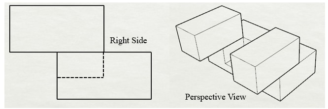
1. First Angle Projection
In the first angle projection it is placed in the first quadrant. The planes of projection are conceived between the watcher and the observed.
Representation:
- The front view is placed in the middle as is the case of figure 2 below.
- The next view, top view, is located at a lower position than the front view.
- The right side view is aligned on an area that is set just below and to the left side of the frontal view.
Application
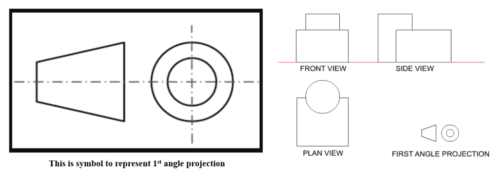
European and Asian countries are the ones who have adopted the use of such products most often.
It is ideal for mechanical and architectural drawings where regional practices standardize the projection method.
2. Third Angle Projection
Then the object is positioned in the third quadrant of the third angle projection. With respect to these planes of projection, the discerned planes of projection are thought to be behind the object.
Representation:
- The view of the front is then pasted at the middle of the object.
- Just as stated earlier, the front view is positioned above the top view.
- Right side view is positioned below and on right side of front view.
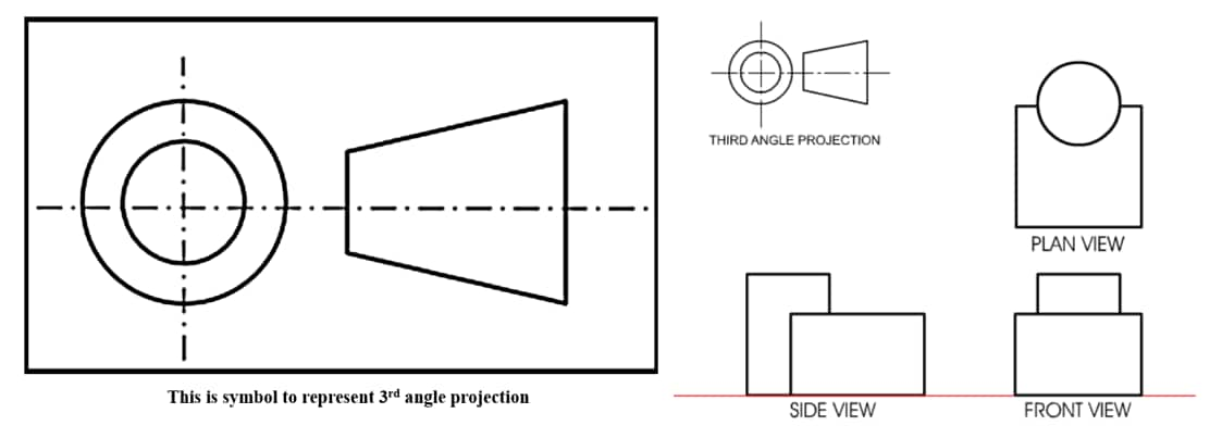
Application
- Standard method of presentation used commonly in United States of America and Canada.
Favored in manufacturing and engineering disciplines as this type of format is easy to follow.
Views: Types, Definitions and Applications
It is essential to comprehend the plan, elevation, section, and exploded views for DAT tests. Students can better visualize and use spatial reasoning through these perspectives by seeing objects from various perspectives. Analyzing shapes, structures, and relationships requires this ability. It facilitates creative problem-solving and successful communication of design ideas. Gaining confidence in these viewpoints is essential for DAT exam success.
- Plan
- Elevation
- Section View
- Exploded View
1. Plan (Top View)
Students can understand the basics of what a plan is for Projection and Views section for DAT exams below:
1a. Introduction
A plan view is a top-down projection that displays the organization and layout of an object or space. Picture yourself glancing down at a house's floor plan, which shows where the walls and rooms are located.
1b. Application
Used in architectural plans, landscape designs, and floor layouts to show the arrangement of spaces and elements from above.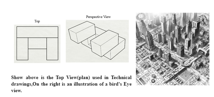
Important Note: Although "Plan" and "Bird's eye view" are sometimes used synonymously, there is little distinction.
Not all bird's eye views are plans, even though all plans are bird's eye views. A plan is an overhead view with precise technical information and a defined function.
2. Elevation (Side View)
An elevation is a technical drawing that shows a structure or object from a vertical perspective. You are staring straight at one side, revealing its height, shape, and details. For example, a building's front elevation shows how its windows, doors, and other architectural details appear from the outside.
Elevations are essential for design visualization since they help to comprehend an object's general shape and dimensions. Stakeholders must understand the design intent.
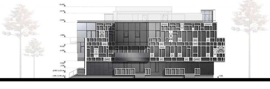
Application: Common in architectural elevations, building facades, and interior design to show height, structure, and vertical relationships.
3. Section View
Aspiring candidates can understand the basics of sections for Projection and Views section for DAT exams below:
3a. Introduction
Section View is a popular visualization technique that helps understand the internal makeup of an object through its cut section. The visual depiction of a theoretical section through a form it offers insights into its composition and organization.
For example, To know a gear's cross-section, the section view makes it easier to see the tooth profiles and material distribution, which are essential for design analysis and understanding of the Functionality of an object.

3b. Objective
- Shows internal features by cutting through the object.
- It can be partial or total, depending on the extent of the cut.
- Typically, it includes hatching or shading to indicate the cut surfaces.
3c. Applications
- Architecture: Used to show internal layouts and structural elements like walls, floors, and staircases.
- Engineering: Highlights internal components of machinery, such as gears and shafts, aiding in the understanding of assembly and function.
- Product Design: Reveals the interior details of a product, which is crucial for manufacturing and assembly processes.
4. Exploded View
Basics of Exploded view for Projection and Views section for DAT exams are given below for students to understand:
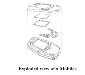
4a. Introduction
An "exploded view" is a technical drawing that displays an object's components in a deconstructed form, demonstrating how a complex object is assembled. As it develops spatial reasoning and an understanding of object building, it is essential for those aspiring to design. Candidates can examine existing designs, conceptualize new products, and properly explain design intent by visualizing the interaction between different pieces. This ability is crucial for creativity and problem-solving in design.
4b. Characteristics
- Illustrates how parts fit together and are assembled.
- Provides a clear understanding of the order and relationship between components.
- Often used in manuals and instructional guides.
4c. Applications
- Assembly Instructions: Common in DIY furniture assembly guides to show how pieces fit together.
- Engineering: Used to document the assembly process of complex machinery.
- Product Design: Assists in visualizing product design and construction, helping troubleshoot and maintain.
Applications of Projection and View
- Engineering Drawings: Used to create detailed blueprints for manufacturing and construction.
- Architecture: Helps in designing buildings with accurate dimensions and perspectives.
- Computer Graphics: Used in 3D modeling, animation, and game design.
- Cartography (Maps): Used for accurate representation of geographic data.
- Medical Imaging: Applied in CT scans, MRI, and X-ray
Important Practice Questions from UCEED/NID
Question:
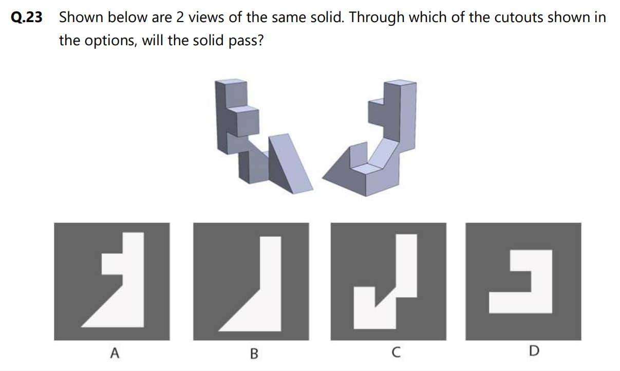
Hint - Here, you must imagine an elevation (side) view of the solid.
Solution:
- Option A: The cutout is too narrow to accommodate both protruding sections.
- Option B: This cutout fits the shape well, allowing the solid to pass through.
- Option C: The cutout doesn't match the shape of the solid; it's too irregular.
- Option D: This cutout has some space, but it won't allow the solid to pass through entirely.
Therefore, the correct option is Option B.
Question:
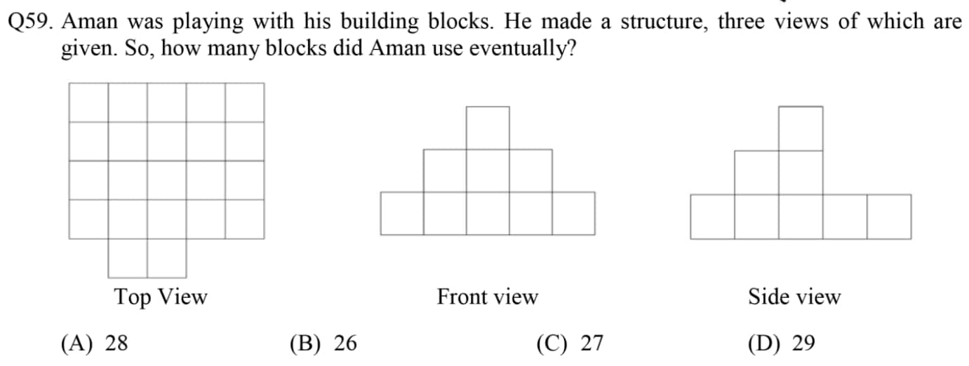
Approach - It is a block counting question but orthographic views are given so you need to imagine this in 3-dimensional.
Solution:
Let's try to solve it step by step:
- Top View: Shows the arrangement of the blocks in a grid-like structure.
- Front View: Reveals how many blocks are stacked vertically in each column from the front.
- Side View: Shows the height from the side, which will confirm how the blocks are stacked.
After considering all three views and combining the information, the total number of blocks Aman used is 27 (Option C).
Question:
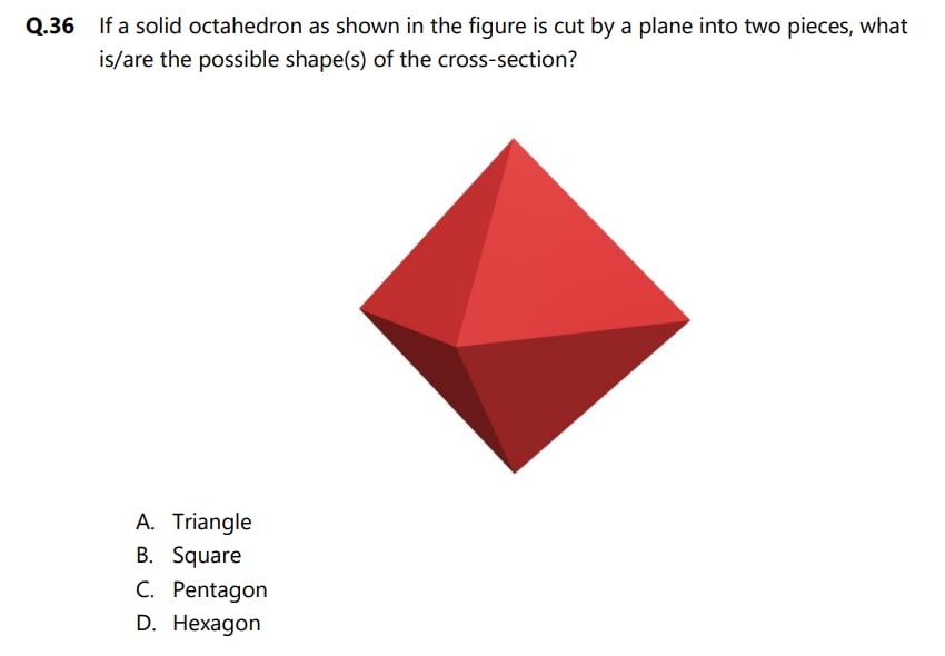
Approach - Visualizing its cross-section by cutting it in planes.
Solution: If this octahedron is cut by a plane into two pieces, the possible shapes of the cross-section depend on how the plane intersects the solid. A plane can cut through the octahedron in various ways, resulting in different cross-sectional shapes. The possibilities include:
- Triangle: When the plane cuts through two opposite vertices, the cross-section can be triangular.
- Square: When the plane cuts through the middle, passing through four faces, the cross-section can be square.
- Pentagon: If the plane cuts through the center, creating an intersection with five faces, a pentagonal cross-section can form.
Thus, the correct possible shapes of the cross-section are:
- Triangle
- Square
- Pentagon
From the provided options, the answer is:
A. Triangle
B. Square
C. Pentagon
Frequently Asked Questions (FAQs)
An "exploded view" is a technical drawing that displays an object's components in a deconstructed form, demonstrating how a complex object is assembled.
A projection is a non-real entity which provides us with the shape of the object in a given orientation onto the specified plane (XY, YZ or XZ). Whereas a view is a physical representation of the object as seen by the viewer.
The only difference between isometric view or drawing and the isometric projection is that in isometric view the object is represented in drawing with actual dimensions using normal scale and in isometric projection objects are symbolized in illustrations with reduced or isometric scale.
Projection means to transfer three-dimensional objects onto two dimensional planes by Orthographic, Isometric and Perspective Projection Techniques.
It is the process of converting a 3D object into a 2D object. It is also defined as mapping or transformation of the object in the projection plane or view plane. The view plane is displayed on the surface.
